Canvas
The function of this control is to draw graphics according to the set data within the control range of 100*100 pixels.
Keywords: monochrome brush 、multicolor brush、refresh
Canvas
Monochrome brush
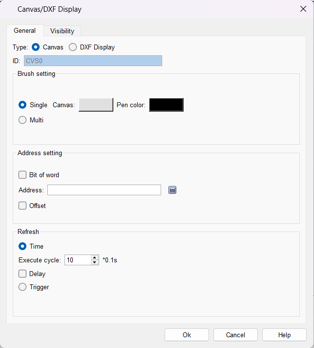
- Canvas color: set the canvas background color
- Brush color: set the brush color
- Address setting: The address is ON to trigger drawing, and a maximum of 10,000 addresses can be set.
- Use the bit index of the word: set a certain bit of the word address to trigger drawing
- Address: Set the bit address to trigger drawing. This address can only use the internal register LB. If you check "Use word bit index", you can only use the internal register LW Bit.
- Address offset: Offset the specified length on basis of the set address as the actual trigger address
Multicolor brush
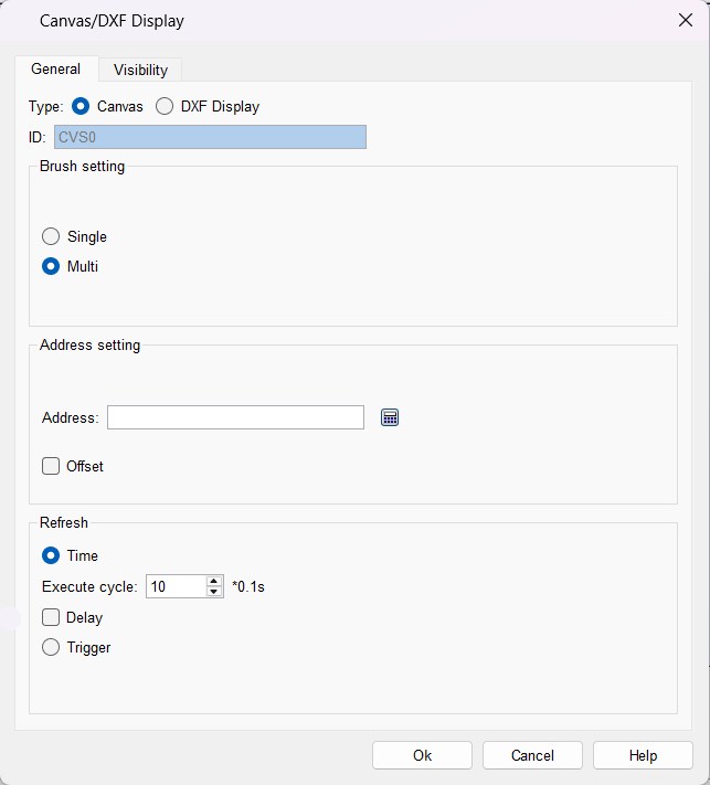
- Address setting: set the word address to trigger drawing, the maximum number of addresses can be set to 10,000, and this address can only use the internal register LW
- Address offset: Offset the specified length on basis of the set address as the actual trigger address
- Others: The background color of the multi-color brush canvas is transparent. When drawing, set the corresponding address to RGB color. For example, set the trigger address to LW0, draw a red point, and the RGB color value is FF4040. Set LW0=FF in sequence according to the RGB color order, LW1=40, LW2 address=40, you can draw a red dot in the control
- Color selection: RGB color comparison table
Refresh
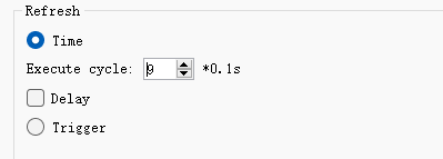
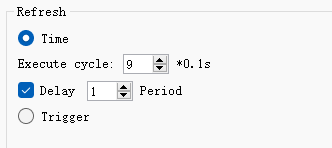
- Timing refresh: set the canvas to refresh at a specified period
- Delay: Refresh after delaying the specified period on basis of timing refresh
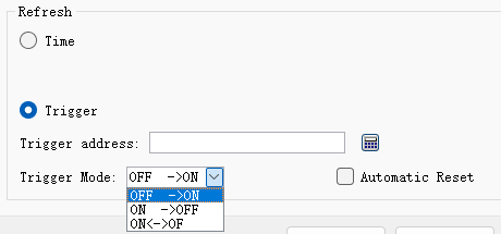
- trigger refresh
o Trigger address: set to use the bit address to trigger the refresh of the canvas
o Trigger mode: set bit address trigger condition
o Automatic reset: Set whether to automatically reset after the bit address is triggered
DXF Display
The DXF display is used to show graphics in DXF files and serialize the graphic data into registers in a specified format for subsequent control.
It supports the identification of the outermost border;
It supports automatic sorting. During automatic sorting, it will detect whether line segments are connected. If they are connected, these line segments will be re - ordered so that they are end - to - end;
It supports layering. Only the data in the default layer is processed, while the data in other layers is only for display and will not be serialized for output;
It supports displaying serial numbers and the direction of line segments;
It supports reversal, which means serializing data in the reverse order;
It supports the concept of groups. Line segments can be combined into groups, and only one group can be selected at a time. Only the data of the current group will be serialized. When a DXF file is opened, a "0" group is created by default, and all line segments are added to this group.
Currently, the supported graphic elements include straight lines and arcs.
(Description of serialized data format:
The first data is the number of line segments, followed by the line segment data. There are two types of data: straight lines and arcs:
Straight line data format: |0 (straight line)|10 (data length occupied by the line)|starting coordinates (x, y floating - point numbers)|ending coordinates (x, y floating - point numbers)|
Arc data format: |1 (arc)|18 (length occupied by the arc)|starting coordinates (x, y floating - point numbers)|ending coordinates (x, y floating - point numbers)|center coordinates (x, y floating - point numbers)|radius (floating - point number)|major or minor arc (1 for major arc, 0 for minor arc, - 1 for 180 degrees)|counterclockwise (1 for counterclockwise, 0 for clockwise)|
Among them, the starting and ending coordinates of a full circle are the same, which are the coordinates of 0 degrees, and the major or minor arc is set to major arc.)
Note:
1. All operations require the use of internal registers.
2. The instructions only apply to the values read when the DXF is opened. After making modifications, you need to reopen the DXF; otherwise, the changes will not take effect.
3. For better compatibility, it is recommended to use the R12 version of DXF. You can export the R12 version of DXF through desktop tools.
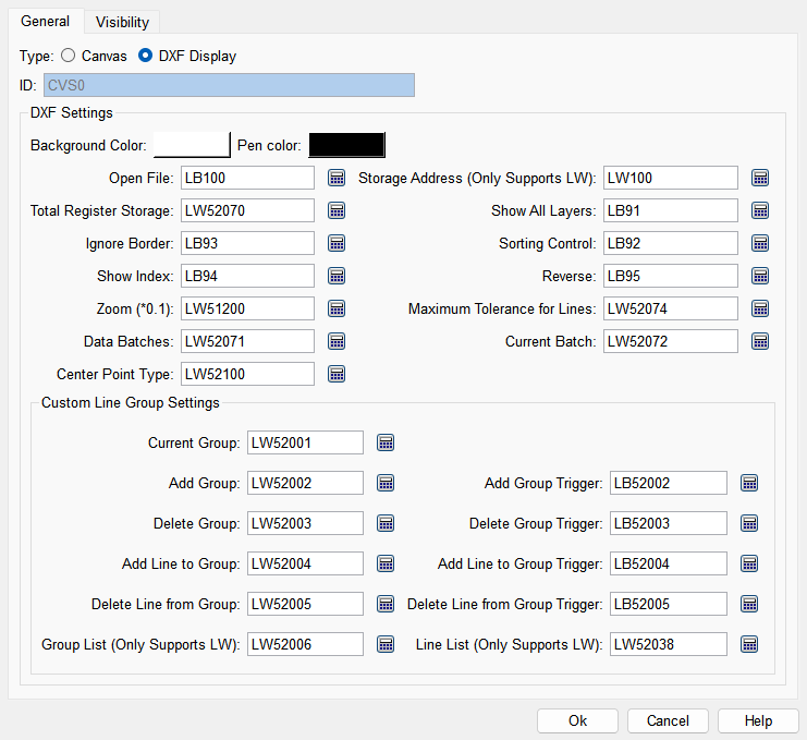
DXF Settings
- Background color: Set the background color of the DXF canvas
- Brush color: Set the color of the brush
- Open file: The trigger address is used to open the dialog box for selecting a DXF file. When it is detected that this register is ON, the selection dialog box will open, and the register will automatically reset to OFF.
- Storage address (Only Supports LW): The starting address of the local register. After the DXF data is read, it will be serialized and stored in the local register in a specified format. It can be copied to the external register through macro instructions.
- Total Register Storage (16 - bit positive integer): The maximum number of registers (LW) that can be used for data serialization. (This register is only checked when reading the DXF file. Note: If the value is 0, no data will be serialized to the specified register.)
- Show All Layers: Display graphics in all layers of the DXF. (Graphics in other layers are only for display; regardless of whether they are displayed or not, they will not be calculated or serialized for output.)
- Ignore Border: When it is ON, the data of the outermost border (polyline in DXF, with 4 vertices) will not be serialized for output and will be displayed in red. (This register is only checked when reading the DXF file.)
- Sorting Control: When it is ON, connected line segments and arcs are considered as a single line; otherwise, they are processed in the order of the lines output by DXF. When it is ON, the lines will be sorted from left to right and top to bottom. (This register is only checked when reading the DXF file.)
- Show Index: When it is ON, the serial numbers will be displayed near the line segments, and the direction of the line segments in the current group will also be displayed.
- Reverse: When it is ON, the line segment data of the current group will be reversed.
- Zoom(*0.1) (16 - bit positive integer): After reading the DXF data, the graphic will first be matched to the size of the control, then scaled to 1/10. When the value of this register is set to 10, the graphic is basically consistent with the size of the control.
- Maximum Tolerance for Lines (32 - bit floating - point number): When the difference between the X and Y values of the start or end points of two line segments is less than this value, the line segments are considered connected. The default value is 0.1 (this value is used when the register value is 0).
- Dta Batches (16 - bit positive integer): The number of LWs occupied after data serialization divided by the "total number of registers for storage", that is, how many blocks the data needs to be divided into. For example, if 3000 LW registers are needed after serialization, and the "total number of registers for storage" is set to 2000, it will be divided into two blocks: 2000 data for the first time and 1000 data for the second time.
- Current Batch (16 - bit positive integer): After the data is divided into multiple blocks as mentioned above, specify the batch of the data block to be used currently. 0 is the first block and 1 is the second block.
- Center Point Type: Move the center point to the visible area of the canvas. There are 6 types: 0: Use the DXF center point; 1: Use the bottom-left corner of the canvas as the center point; 2: Use the top-left corner of the canvas as the center point; 3: Use the top-right corner of the canvas as the center point; 4: Use the bottom-right corner of the canvas as the center point; 5: Use the center of the canvas as the center point.
Custom Line Segment Group Settings
- Current Group (16 - bit positive integer): The serial number of the currently selected group
- Add Group (16 - bit positive integer): Enter the serial number of the group to be added.
- Add Group Trigger: When it is ON, a group will be added according to the serial number entered in the "Add group" register, and the register will automatically reset to OFF.
- Delete Group (16 - bit positive integer): Enter the serial number of the group to be deleted.
- Delete Group Trigger: When it is ON, the group with the serial number entered in the "Delete group" register will be deleted, and the register will automatically reset to OFF.
- Add Line to Group (16 - bit positive integer): Enter the serial number of the line segment to be added to the current group.
- Add line to Group Trigger: When it is ON, the line segment with the serial number entered in the "Add line segment to group" register will be added to the current group, and the register will automatically reset to OFF.
- Delete Line from Group (16 - bit positive integer): Enter the serial number of the line segment to be deleted from the current group.
- Delete Line from Group Trigger: When it is ON, the line segment with the serial number entered in the "Delete line segment from group" register will be deleted from the current group, and the register will automatically reset to OFF.
- Line List (Only Supports LW): Display the list of line segments in the current group, in ASCII format, separated by commas, with a maximum length of 64 characters (requiring 32 LW registers).
- Group List (Only Supports LW): Display the list of existing groups, in ASCII format, separated by commas, with a maximum length of 64 characters (requiring 32 LW registers).
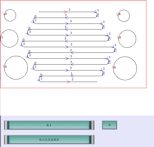
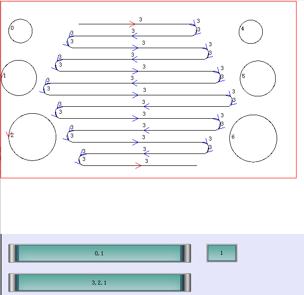
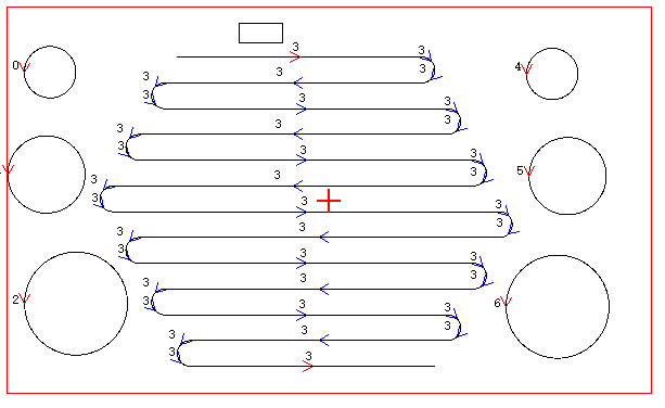
The running effect is shown in the following figures