1. EPID guide
1. EPID guide
Please check with our enginner or sales what kind of PLC mode support the EPID .
1.1. Instruction description
EPID closed-loop control has the following characteristics:
The output can be selected as D register analog or Y/M switch.
A set of suitable PID parameters can be obtained through self-tuning, and these parameters can be manually adjusted to achieve better control effects.
The critical oscillation method is used for self-tuning, which can start from any temperature. It is recommended that users manually control the system to approach the target value before starting self-tuning, which can shorten the self-tuning time. During the self-tuning period, certain parameters may be automatically adjusted according to the situation.
You can set the forward and reverse actions of the EPID wizard: In temperature control situations, the forward action is generally used for cooling control, and the output increases as the measured value increases; Reverse action is generally used for temperature control, and as the measured value increases, the output decreases.
There are three operating modes available for PID mode, which can be switched between during operation. The conventional control mode or adaptive fuzzy PID control mode is controlled by EPID wizard to output, and the output is specified by the user in manual mode. When manually switching to automatic mode, the EPID wizard will perform a smooth transition based on the output size at the time of switching.
If the parameter input is illegal, the corresponding error code flag will be set, and the previous parameter value will be maintained for operation output.
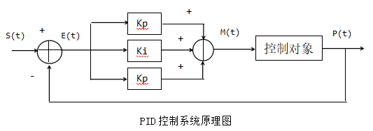
图1 PID control rules
E(t) = S(t) - P(t) (1)
M(t) = Kp[E(t) + 1/Ti∫E(t)dt + Td dE(t)/dt] (2)
(2)Kp, Ti, and Td represent the proportionality coefficient, integration time, and differentiation time, respectively.
IO quantity: The calculation result is the time it takes for the Y/M port to be turned on in one sampling period, which is equivalent to the pulse width time of the endpoint output. Duty cycle=M (t)/T * 100%, where T is the sampling time.
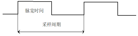
图2 PID sampling period
1.2. 2. parameter setting
Users can create a PID control loop through the EPID wizard on PLC software.
In the setting interface of the EPID wizard, relevant parameters can be entered. Clicking on 'Write to PLC' in monitoring mode can write the parameters to the corresponding D register. When downloading the program, the data set on the interface will also be written into the corresponding D register. Of course, users can also use instructions such as movf to write parameters into the corresponding registers before enabling EPID. During use, users can modify the relevant parameter registers at any time. If the user modifies the contents of the register, the parameters can be read into the wizard by reading the PLC in monitoring mode.
The EPID wizard parameter setting is divided into several steps, and the following is the specific setting interface:
1.2.1. Circuit settings
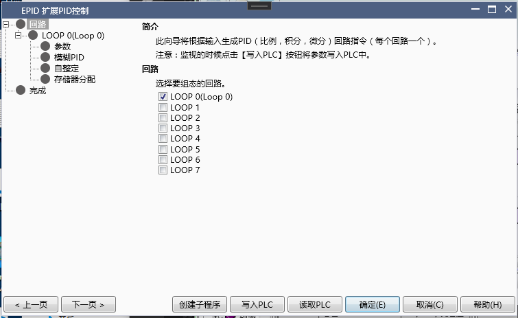
图3 PID Circuit settings
♦ Loop: The EPID wizard supports creating 8 PID loops, select the loop number to be created here.
1.2.2. Basic setting
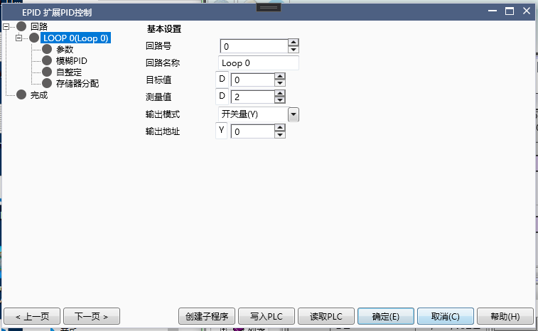
图4 PID basic setting
♦ Circuit number and circuit name: Corresponding to the previous circuit settings, the circuit name can be defined by oneself.
♦ Target value: The data type is DWord. The set value SV for PID control.
♦ Measurement value: The data type is DWord (double letter). The measured value PV of PID control.
♦ Output mode: divided into switch Y/M and analog D.
♦ Output address: Select the corresponding output address based on the output mode.
1.2.3. parameter setting
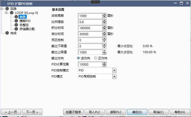
图5 PID parameter setting
♦ Sampling time: in milliseconds. The sampling time determines the period of PID sampling and calculation. If switch output is selected, the sampling time is also the period of the port output.
♦ Proportional gain: Proportional control.
♦ Integral time: in milliseconds. The longer the integration time, the smaller the integration effect.
♦ Differential time: in milliseconds. The larger the differential time, the greater the differential effect.
♦ Control dead zone: When the deviation between the measured value and the target value is less than the control dead zone, PID control does not work to prevent unnecessary calculations caused by the jitter of the measured value PV during steady state
♦ Output upper and lower limit values
Switching output: The output upper limit is less than or equal to the sampling time, and the ratio of the output upper limit to the sampling time is the maximum output duty cycle, which is equivalent to the output upper limit of the heating equipment. Similarly, the lower limit determines the minimum output duty cycle.
Analog output: The PID output result is between the upper and lower limits.
♦ Output direction
Reverse direction: As the measured value PV decreases, the output MV increases. Temperature control is used for temperature rise control in temperature controlled environments.
Positive direction: As the measured value PV decreases, the output MV decreases. Temperature control is used for cooling control in temperature controlled environments.
♦ PID calculation range: When the deviation between the target value SV and the measured value PV is less than the PID calculation range, PID control takes effect. Otherwise, based on the deviation and direction of action, output according to the maximum or minimum limit.
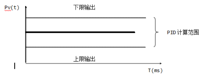
图6 PID caculation range
♦ PID control mode: Determine whether the control mode is PID or PI or P control. Different control modes are suitable for different scenarios. PID control is generally used for temperature control, while PI control is generally used for pressure and flow control.
♦ PID mode: Determine the different modes of PID operation, please refer to the instructions for specific information.
1.2.4. Adaptive Fuzzy PID
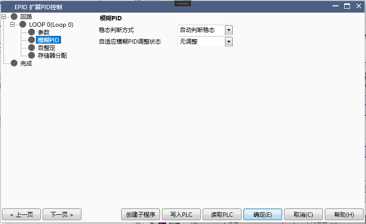
图7 PID PID Calculation Range
♦ Steady state judgment method: Automatic judgment is selected by default, and EPID will automatically judge whether the system has reached steady state. After reaching steady state, adaptive fuzzy PID parameter adjustment calculation will be performed. If not checked, the user needs to manually input 1 into the adaptive PID adjustment status register to perform adjustment calculations.
The steady-state condition for automatic judgment: the deviation remains within 20 ° and oscillates back and forth for more than two cycles. If the deviation exceeds 20 °, the steady-state judgment will be restarted until the steady-state is reached. If the user chooses to manually input to enable adaptive adjustment, it is also necessary to try to keep the system in steady-state conditions before manually enabling adjustment calculation. The smaller the steady-state oscillation amplitude, the shorter the adjustment time, otherwise the adjustment time may become longer or even fail.
♦ Adaptive fuzzy PID adjustment state: When automatically judging steady state, the register corresponding to the offset 26 word is read-only, 1 represents in adjustment state, 0 represents no adaptive adjustment and PID control is performed based on the initial parameters input by the user. When the user manually judges, the register only writes. Writing 1 represents adaptive adjustment, and clearing 0 represents control according to the initial parameters input by the user.
1.2.5. Self tuning
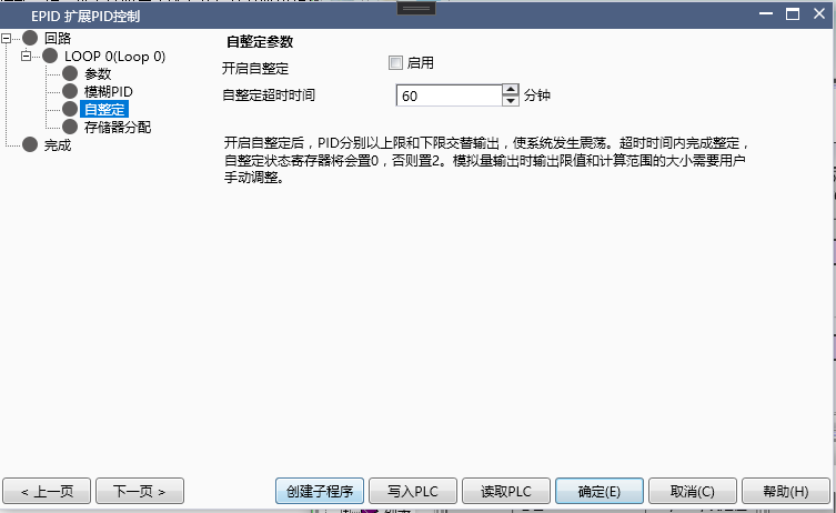
图8 Self tuning
♦ Enable self-tuning: In non monitoring mode, you can check whether to enable it and click to write to the corresponding register of the PLC. In monitoring mode, the current self-tuning status can be displayed.
♦ Self setting timeout: in minutes. Self-tuning maximum duration to prevent the self-tuning time from being too long. If self-tuning is successful, set the corresponding register to 0; if self-tuning fails, set the corresponding register to 2.
First, set the self-tuning status register to 1, and then enable the PID to automatically perform self-tuning. After tuning is complete, the PID will automatically perform regular control. During the self-tuning period, the PID calculation range and output upper and lower limits will be automatically adjusted based on the temperature rise.
1.2.6. Memory allocation
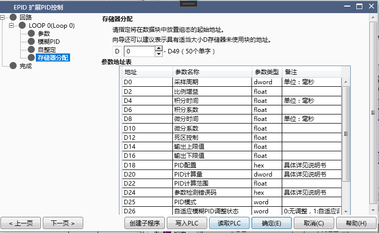
图9 Memory allocation
♦ Starting address: Specify the starting address of the D register used to store PID parameters. At present, PID requires 50 D registers, totaling 100 bytes, which can be set in the power-off hold area by users.
Note that these addresses are continuous and cannot be used elsewhere in the project after confirmation, otherwise it will cause the PID to malfunction.
1.3. Register allocation table
W represents the parameter input by the user; R represents the parameter calculated by the instruction and read only by the user; R/W can be inputted by the user or automatically written by the program.
| Address | Parameter Name | Parameter Type | R/W | Remarks |
|---|---|---|---|---|
| 0 | Sampling time | DWord | W | Unit: ms. The default value for switch quantity is 1000ms, and the default value for analog quantity is 0 (must be specified by the user) |
| 2 | Proportional gain | float | R/W | Set to 0, indicating no proportional effect |
| 4 | Integral time | float | R/W | Unit: ms. Set to 0, indicating no integral effect. |
| 6 | Integration coefficient | float | R | Integration coefficient=proportional gain X sampling time ÷ integration time. The coefficients actually involved in the operation are read-only |
| 8 | Differential Time | Float | R/W | Unit: ms. Set to 0, indicating no differential effect |
| 10 | Differential coefficient | float | R | Differential coefficient=Proportional gain X Differential time ÷ Sampling time. The coefficients actually involved in the operation are read-only |
When the deviation between the measured value and the target value is within the dead zone, PID does not calculate
| 14 | Output upper limit value | float | R/W | Switch value corresponds to the maximum output duty cycle, which is also the output value during self-tuning. |
| 16 | Output lower limit | float | R/W | The switch value corresponds to the lowest output duty cycle and is also the output value during self-tuning. |
| 18 | PID configuration | hex | W | User configurable options during PID control process, please refer to the instructions for specific information. |
| 20 | PID calculation quantity | DWord | R | Only the switch quantity is valid, storing the port on-time in one sampling cycle. Invalid for analog output |
| 22 | PID calculation range | float | R/W | deviation range within which PID calculation takes effect. |
| 24 | Parameter detection error code | hex | R | The error code is used to indicate the validity of the input parameters after the wizard is turned on. Please refer to the instructions for specific information. |
| 25 | PID mode | Word | W | Used to switch the running mode of PID. 0: PID automatic control mode 1: User manual control mode 2: Adaptive fuzzy PID control. Other integers: Pause PID control (output remains unchanged) |
| 26 | Adaptive Fuzzy PID Adjustment Status | Word | R/W | Used to control or indicate the adaptive adjustment status. 0: No adjustment state 1: Adaptive adjustment state. Enter other values in an unadjusted state |
| 27-33 | Reserved Area | Program Reserved Area. | ||
| 34 | self-tuning status | word | R/W | 0: self-tuning completed 1: self-tuning in progress 2: self-tuning failed. The input of other values is invalid. |
| 36 | Self setting timeout | dword | W | Unit: min. |
| 40-49 | Reserved Area | Program Reserved Area. |
Note:
1)After creating the EPID wizard for the first time, the configuration interface automatically fills in the default value for switch output, and the default value for analog output is 0, which needs to be manually specified by the user (otherwise the corresponding PID parameter detection error code will be set).
2)All parameters can be written into the corresponding D register by writing them to the PLC in monitoring mode. If the user manually changes the parameters in the D register, they can upload them to the wizard by reading the PLC. When downloading, the parameters in the current wizard will be automatically written to the PLC. If the user manually modifies the parameters in the D register in the ladder diagram, they need to read and download them first to prevent the loss of modified information in the ladder diagram.
3)When manually writing parameters in a ladder diagram, please pay attention to the data types of each parameter.
4)Users must assign a value to the register with offset address 25 in the ladder diagram in order to switch to manual/automatic mode/adaptive fuzzy PID mode. You can assign values during runtime to switch modes. When switching from manual mode to automatic mode, if there are PID parameters, the integral term will be automatically calculated to ensure a smooth transition.
1.4. EPID usage process
1.4.1. a) PID conventional control mode (without self-tuning)
1) Parameter settings: refer to the instructions for precautions
♦ Set sampling time
♦ Set PID parameters
♦ Set output upper and lower limits
♦ Set PID calculation range
♦ Set PID control mode and direction
♦ Allocate storage first address
2) PID mode selection: PID mode register clear 0
3) Enable EPID command
4) During the process, the EPID instruction can be directly disabled to turn off PID control, or an integer greater than 2 can be written to the PID mode register to pause PID control and maintain the output unchanged.
1.4.2. b) PID conventional control mode (self-tuning)
1) Parameter settings: refer to the instructions for precautions
♦ Set sampling time
♦ Set output upper and lower limits
♦ Set PID calculation range
♦ Set PID control mode and direction
♦ Set self-tuning timeout period
♦ Set self-tuning offset amplitude
♦ Write 1 to the self-tuning status register
♦ Allocate storage first address
2) PID mode selection: PID mode register clear 0
3) Enable EPID command
4) During the process, the EPID instruction can be directly disabled to turn off PID control, or an integer greater than 2 can be written to the PID mode register to pause PID control and maintain the output unchanged.
5) The self-tuning success status register is cleared to 0, otherwise it is set to 2.
1.4.3. c) Adaptive fuzzy PID control mode
1) Parameter settings: refer to the instructions for precautions
♦ Set sampling time
♦ Set output upper and lower limits
♦ Set PID calculation range
♦ Set PID control mode and direction
♦ Set whether to automatically determine steady state
♦ Set initial PID parameters
♦ Allocate storage first address
2) PID mode selection: PID mode register write 2
3) Enable EPID command
4) If the steady state is automatically determined, setting the status register to 1 indicates entering the steady state adjustment stage. For non automatic determination, users need to manually set it to 1 to enter the adjustment stage.
5) During the process, the EPID instruction can be directly disabled to turn off PID control, or an integer greater than 2 can be written to the PID mode register to pause PID control and maintain the output unchanged.
1.4.4. d) PID manual control mode
1) Parameter settings: refer to the instructions for precautions
♦ Set sampling time
♦ Set PID parameters (optional)
♦ Write the expected output quantity into the PID calculation quantity offset by 20 words. Write the expected output quantity to the output address in the basic settings using analog signals.
♦ Allocate storage first address
2) PID mode selection: PID mode register write 1
3) Enable EPID command
4) During the process, the EPID instruction can be directly disabled to turn off PID control, or an integer greater than 2 can be written to the PID mode register to pause PID control and maintain the output unchanged.
5) If PID parameters are set, a smooth transition will occur when switching to the regular control mode based on the set PID parameters
1.4.5. e) Mode switching during PID operation
♦ When switching to any mode, it is necessary to simultaneously set the relevant parameters and configurations that need to be set in that mode.
♦ It can switch from normal mode or adaptive mode to manual mode during operation.
♦ It can switch from manual mode to automatic mode or adaptive mode, and has smooth transition processing.
♦ The conventional control and adaptive control modes can also be switched to each other, and when switching to the adaptive mode, a steady-state judgment will be performed again.
1.5. attention
1.5.1. a) Sampling time
1) Legitimacy judgment: The sampling time must be greater than the scanning period. The sampling time of the switch quantity must be greater than or equal to the output upper limit. If the legality judgment is not met, the corresponding bit in the parameter error detection code will be set to 1, and the input will be cleared automatically if it is valid.
2) In situations where temperature control changes slowly, it is generally recommended to sample for around 1000ms; In situations where pressure, flow rate, and other changes occur rapidly, it is generally recommended to wait around 100ms.
3) Try not to change the sampling time during operation, especially in the stable phase, as this can cause changes in PID parameters, leading to fluctuations in PID control.
1.5.2. b) Output upper and lower limit values
1) Legitimacy judgment: The output upper limit should be greater than the output lower limit. When outputting switch values, the upper limit of the output should be less than or equal to the sampling time, and both the upper and lower limits should be greater than or equal to 0. If the legality judgment is not met, the corresponding bit in the parameter error detection code will be set to 1, and the input will be cleared automatically if it is valid.
2) If the operating power of the device is unclear, the upper limit can be appropriately reduced during trial operation. When switching on or off, the wizard interface will calculate the output duty cycle based on the sampling time and upper and lower limits for reference.
3) Appropriate upper and lower limit output values will shorten the self-tuning process. If the upper limit value is too large or the lower limit value is too small, it will cause the system to oscillate excessively during alternating output, resulting in a longer self-tuning time. If the upper limit value is too small or the lower limit value is too large, it may cause the system to be unable to oscillate back and forth near the target value, resulting in self-tuning failure.
1.5.3. c) PID caculation range
1) Legitimacy judgment: The PID calculation range must be greater than the control dead zone. If the legality judgment is not met, the corresponding bit in the parameter error code will be set to 1, and the input will be cleared automatically if it is valid.
2) The smaller the PID range, the larger the range of full power output, and the faster it reaches the target value. For systems with large inertia and hysteresis, it may also cause significant overshoot. Initially, the PID range can be increased, and later, according to the adjustment curve, the PID range can be appropriately reduced to accelerate the adjustment speed.
1.5.4. d) PID setting
| Bit | 15-4 | 3 | 2 | 1 | 0 |
|---|---|---|---|---|---|
| Value | reserve | SD | TYPE | Dir |
1) Dirk: 0: Reverse action 1: Forward action. When reversing, E=Sv PV, commonly used for heating control in temperature controlled situations. During normal operation, E=Pv - Sv, which is commonly used for cooling control in temperature controlled situations.
2) TYPE: 0: PID control 1: PI control 2: P control. PID control is generally suitable for post coupling with large hysteresis, such as temperature control, while PI control is suitable for situations with relatively fast speeds, such as pressure and flow.
3) SD: 0: Enable steady-state automatic judgment 1: Disable steady-state automatic judgment. Adaptive fuzzy PID control first requires the user to reach a steady state based on a set of empirical parameters, which automatically determines the steady state by default. If set, the automatic steady-state judgment will be turned off, and the user needs to enable adaptive PID adjustment by themselves.
1.5.5. e) PID mode
1) PID conventional control mode: When in this mode, the PID adjusts and controls according to the PID parameters input by the user. In this mode, the self-tuning status register can be set to 1 during operation to initiate self-tuning.
2) PID manual control mode: When in this mode, the PID outputs according to the user's input and output. If there are PID parameters at this time, smooth transition processing will be performed based on the PID parameters when switching to normal mode or adaptive fuzzy PID mode.
3) Adaptive Fuzzy PID Mode: When in this mode, the PID performs steady-state judgment based on the initial PID parameters provided by the user, and automatically or manually enters the adaptive adjustment state after entering steady state.
4) Input a positive integer greater than 2, and the PID will enter a pause calculation state. At this time, the output remains unchanged and no PID calculation will be performed.
1.5.6. f) Self-tuning
1) The self-tuning timeout period shall not be less than 60 minutes, which is only used for timeout judgment and will not affect the actual self-tuning effect.
2) Before starting self-tuning, confirm whether the output upper and lower limits are roughly reasonable. An excessively large upper limit may cause overshoot, while an excessively small upper limit may prevent the system from oscillating back and forth around the target value.
3) It is recommended to use manual mode output before starting self-tuning to make the measured value close to the target value. Enabling self-tuning at this time will greatly shorten the self-tuning time.
1.5.7. g) Adaptive Fuzzy PID Control
1) Overview: Adaptive fuzzy PID control continuously adjusts the three parameters Kp, Ki, and kd through a certain inference process based on the current deviation e and the difference ec between the current deviation and the previous deviation. The adjusted parameters are used to calculate the output using an incremental PID calculation formula.
2) Usage process:
Ø Parameter settings: sampling time, PID calculation range, output upper and lower limits. When the deviation is greater than the PID calculation range, output according to the maximum or minimum power. Appropriate output limits and PID calculation range can enable the system to enter steady state as soon as possible.
Initial PID parameters: The user provides a set of initial PID parameters, and by adjusting this set of initial parameters, the system reaches steady state, requiring steady-state judgment.
Ø Adaptive PID adjustment: After entering this stage automatically or manually, the PID parameters will be automatically adjusted to achieve the desired control effect.
Attention: The time required to enable adaptive adjustment before reaching the steady-state requirement will increase and there is a higher possibility of unsuccessful adjustment.
3) Steady state adjustment of initial PID parameters
PID parameter reference for temperature control occasions:
| Sampling time (ms) | Proportional gain | Integration time (ms) | Differentiation time (ms) |
|---|---|---|---|
| 500-2000 | 0.1-2 | 10000-30000 | 0-10000 |
Note: Determine the magnitude of PID parameters based on the comparison of actual input-output dimensions. For example, the size range of p is determined by comparing the output range and input range. In temperature situations, the output quantity is between the upper and lower limits. Comparing the approximate range of temperature changes is not difficult to determine the size range of P.
Ø The empirical method is used to adjust parameters. The following provides adjustment methods for temperature control scenarios for reference only. In practice, it may require repeated adjustments to achieve the desired effect.
A. Adjust the proportional coefficient Kp upwards from 0.1, so that the system can oscillate back and forth near the target value without divergence, and record the Kp value at this time. Adjusting the value of Kp can change the magnitude of oscillations, but if it is too large, it will increase the number and amplitude of oscillations in the system, and even lead to divergence.
B. The integration time gradually decreases from a larger value (the smaller the integration time, the stronger the integration effect) until the system can stabilize within a certain number of oscillations. Adjusting the value of TI can change the number of oscillations during the stabilization process, but excessive values can also cause significant oscillations in the system.
C. Generally, the differential time is set to 0. Adjust the differential time gradually to increase and reduce the oscillation amplitude of the system. Adjusting Td can make the changes smoother, reduce peak and oscillation frequency, but it will make the adjustment time longer and the system response speed slower.
4) Steady state judgment: If the deviation oscillates back and forth for more than two cycles within 20 °, it is considered to have reached steady state, and 1 will be automatically filled in the adaptive PID regulation state register. If the user chooses to manually determine, they need to fill in 1 in the register themselves to initiate the adjustment process. During the automatic steady-state judgment period, if the temperature deviation exceeds 20 °, the steady-state judgment will be restarted until it is confirmed. Before reaching steady state, the PID parameters can be adjusted at any time to accelerate the speed of entering steady state.
5) Adaptive PID regulation stage: EPID will automatically fine tune the PID parameters to achieve the desired state during this stage.
Attention:
The method of readjusting the initial parameters for steady-state judgment: When the user manually judges, directly clear the adjustment status register and adjust the initial parameters. When making automatic judgments, it is necessary to first switch to manual judgment, then clear the status register, adjust the initial parameters, and then switch to automatic steady-state judgment.
Change target value: If the deviation from the current sampling value exceeds 20 ° after changing the target value, the automatic judgment mode will clear the status register, and control will be carried out with the initial PID parameters to re evaluate the steady state. Therefore, please note that after changing the target value, it may be necessary to adjust the output upper and lower limits and PID parameters according to the actual situation to make the system enter steady state faster. In the case of manual judgment, users need to clear the status register themselves and manually write 1 to start adjustment again after reaching steady state, otherwise the adjustment effect may not be ideal.
1.5.8. h) Parameter error code detection
| Bit | 15-3 | 2 | 1 | 0 |
|---|---|---|---|---|
| Value | reserve | RA | HL | ST |
ST: 1 represents invalid sampling time, 0 represents valid
HL: 1 represents invalid input high or low limit, 0 represents valid
RA: 1 represents invalid PID calculation range, 0 represents valid
Note: When the input parameters are invalid for the first time, the PID will not perform any calculations and will not output any output. During the running process, if the parameter changes are illegal, the EPID wizard will maintain the last valid value for calculation and output, and there will be corresponding error code prompts. For specific illegal information, please refer to the notes on the respective parameters.
1.6. PID example
1.6.1. 一、Electric heating iron temperature control case
Scenario: Use switch Y to control the temperature of an electric heating iron to maintain a constant temperature. The room temperature is 25 ℃, and the target temperature is set to 150 ℃.
1.6.1.1. a)parameter setting:
Sampling time 1000ms;
Set the proportional, integral, and derivative time to 0 and obtain the parameters through self-tuning;
Set the output upper limit to 500 and the lower limit to 0;
Reverse direction;
The PID calculation range is 300, but the actual calculation range is between 1200-1800;
Enable self-tuning;
Self setting timeout of 80 minutes;
The self-tuning assignment offset is 150, which means that when the maximum peak temperature exceeds 165 ℃ during self-tuning, the output upper limit will be automatically reduced to minimize the peak offset;
Storage starting address D1000
1.6.1.2. b)Self tuning and PID regulation sequence
- Start heating from room temperature of 25 ℃, complete self-tuning in about 18 minutes, and finally stabilize the temperature within 150 ℃± 1 in about 28 minutes. After self-tuning is completed, there will be a period of oscillation before stabilizing.
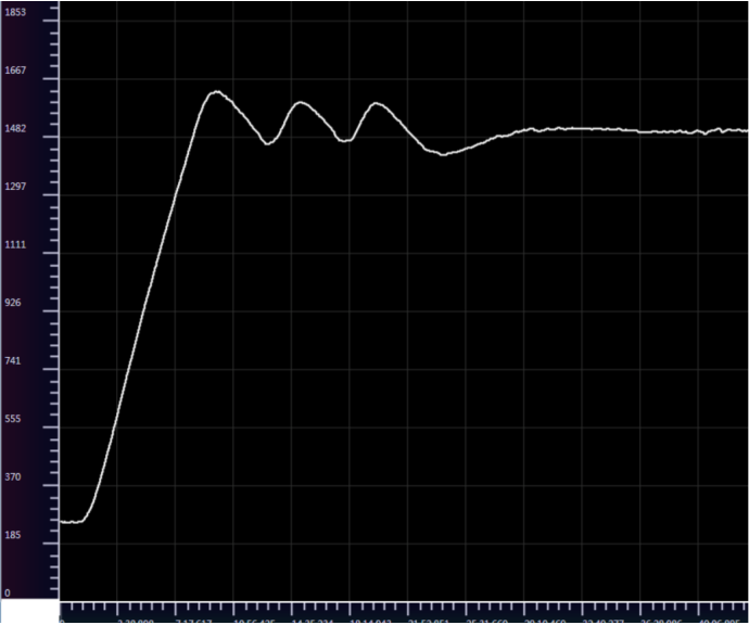
图10 Self tuning process curve
- Change the target value to 100 ℃, and after about 20 minutes, it tends to stabilize rapidly at the new target value.
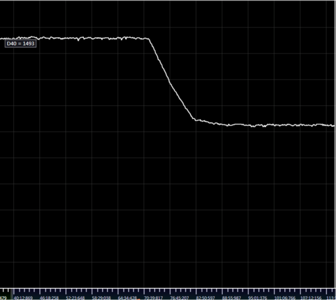
图11 Target Value Change Curve
- Change the target value to 180 ℃, and after about 20 minutes, the temperature tends to stabilize. There is a fluctuation of approximately ± 4 ℃ at the new target value, and then tends to stabilize
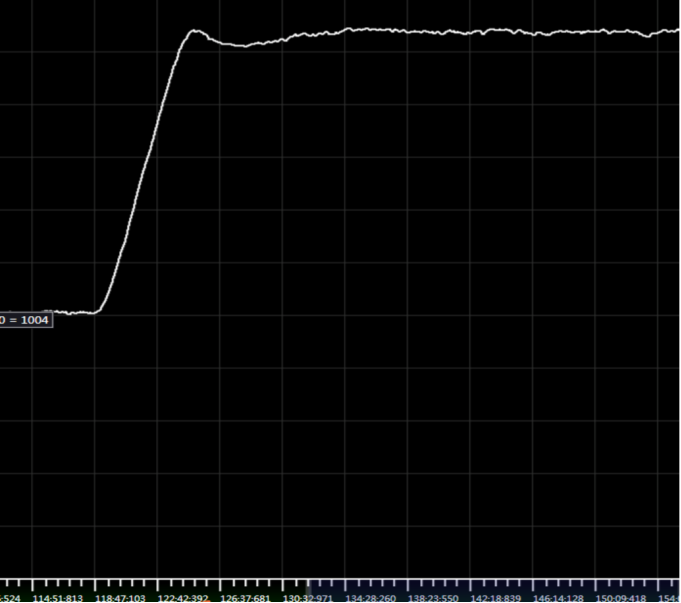
图12 arget Value Change Curve
Analysis:
In this example, after the target temperature of 150 ℃ is self-tuning, there will be a large oscillation for one cycle, with a deviation of approximately ± 7 ℃. Observing that the oscillation amplitude during self-tuning is relatively small in this example, the output upper limit can be increased and self-tuning can be carried out again.
If there is a large amplitude of oscillation during subsequent adjustments, the proportional gain can be appropriately reduced, and the differential time can be appropriately increased to reduce the oscillation speed. If there are a large number of oscillations when approaching the target value, please increase the differentiation time appropriately.
If there is a self-tuning failure, it indicates that the self-tuning time is greater than the timeout period, which may be due to the system's inability to heat up or cool down due to heating power or other reasons. Otherwise, please increase the timeout period.
1.6.2. 二、Pipeline heating compressed air
Scenario 1: Using analog 4-20mA output and signal amplification module, control the compressed air temperature flowing in the heating pipeline of the heating equipment to maintain a constant level. The target temperature is 500 ° C.
1.6.2.1. a)parameter setting:
Expansion module 4-20mA output, digital range 0-32767
Sampling time of 100ms;
Proportional, integral, and derivative time are all set to 0;
Set the output upper limit to 21000 and the lower limit to 0; (The output upper limit power is about 65%)
Reverse direction, dead zone control 2, control method PID;
The PID calculation range is 400, but the actual calculation range is between 4600-5400;
Enable self-tuning;
Self setting timeout of 80 minutes;
Storage starting address D1000
1.6.2.2. b)Self tuning and PID regulation sequence
- Self adjust from room temperature for 4 minutes, stabilize for 1 minute, and reach 500 ° C for a total of 5 minutes.
Setting parameters: P: 34.27956 I: 25350 D: 6084. After stabilizing, the temperature remains within ± 1 ° C.
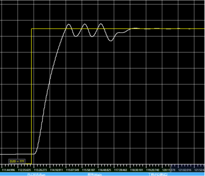
图13 Self tuning process curve
- Heat from 50 ° C to 500 ° C under the parameters obtained from self-tuning. Adjust the stabilization time to about 2 minutes, and the control effect is good.
In this example, due to the heating of flowing compressed air, the system response is faster and the self-tuning speed is much faster compared to general temperature control scenarios. After observing the curve, the speed of stabilizing can be further accelerated by narrowing the PID calculation range.
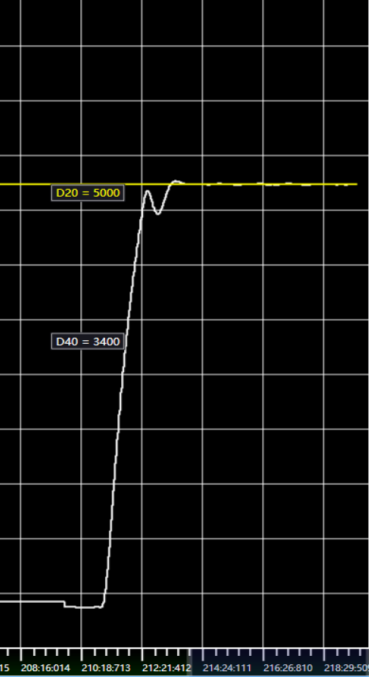
图14 Target Value Change Curve
Under the previously self-tuning parameters, first use manual mode to control the system to reach a certain measurement value, and then switch to automatic mode. When switching from manual mode to automatic mode, the wizard will automatically perform smooth transition processing.
Heat up to 460 in manual mode at 22000 (65% power) and switch to automatic mode. After switching to automatic mode, the system temperature tends to stabilize after fluctuating. Further reduction of fluctuations can be achieved by increasing the power of manual control.
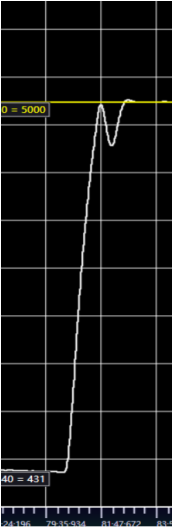
图15 Target Value Change Curve
Heating to 490 ° C in manual mode at 22000 (65% power), then switching to automatic mode, fluctuations still exist, but the speed of stabilization has increased.
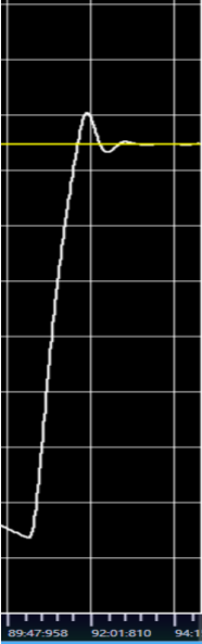
图16 Target Value Change Curve
Manually control first, then switch to automatic control to achieve better stability. The manually controlled power can be adjusted appropriately to make the transition smoother.
- On the basis of this configuration, adjusting the valve opening during the stable phase can cause the system to oscillate, and the PID adjustment can be observed.
Suddenly reducing the gas valve caused the system temperature to rise by 10 ° C, and after a round of oscillation within 1 minute, the system stabilized again. PID regulation has the ability to resist disturbances in steady state, which can be further enhanced by adjusting the differential time.
图17 Target Value Change Curve
Scenario 2: Using switch output and adaptive fuzzy PID control to maintain a constant temperature of compressed air flowing in the heating pipeline. The target temperature is 150 ° -250 ° -400 ° -500 °.
1.6.2.3. a)parameter setting:
Sampling time 500ms;
Proportional, integral, and derivative time are all set to 0;
Set the output upper limit to 200 \ -300 \ -400 \ -400 and the lower limit to 0 respectively;
Reverse direction, dead zone control 2, control method PID;
PID calculation range 400 \ -500 \ -600 \ -700;
Set the proportional gain to 0.2, the integration time to 20000ms, and the differentiation time to 0. The initial parameters enable the system to enter steady state at various target values;
Set the PID mode to 2, select the adaptive fuzzy PID control mode, and automatically determine the steady state;
Store starting address D1000;
1.6.2.4. b)The following is the actual control curve chart
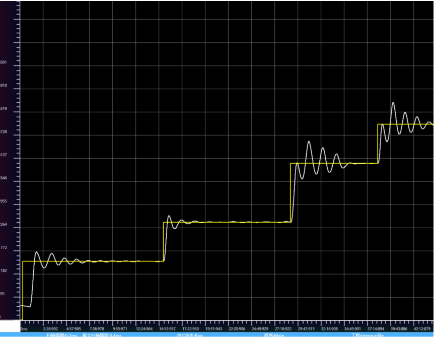
图18 Control Curve Chart
Analysis and Summary
When the target values are 200 ° and 300 °, they enter steady state after two oscillations within 20 ° under the initial PID parameter control, and then enter the parameter adaptive adjustment stage.
When the target temperature switches to 400 ° C and 500 ° C, due to the low output upper limit, the first heating amplitude is low, resulting in more oscillations and a slower speed of entering steady state. By adjusting the output upper limit value and PID calculation range, oscillations can be generated during the first heating, and the proportional gain can be appropriately adjusted to reduce the amplitude of oscillations.
When the target temperature switches to a higher 500 ° C, the output upper limit should be increased, and the proportional gain should be adjusted according to the situation to ensure that the system's oscillation amplitude meets the steady-state requirements.