Preface
R8 series AC servo drive
Instruction manual V1.3.5
Release date: May 23, 2024
Shenzhen, China
preface
Readers
This user manual is about Samkoon R8 series AC servo drive. It introduces the installation, operation, and debugging process of the R8 driver from safety precautions, product information, installation and wiring, display and keyboard operation, operation, parameter settings, fault alarms, and other aspects.
This document is mainly applicable to the following personnel::
- Technical support engineer;
- Equipment installation engineer;
- Equipment maintenance engineer.
Sign Definition
In this document, the following signs may appear and represent the following meanings:
sign | description |
| Danger signs, misoperation may result in serious consequences such as endangering personal safety, equipment safety, or environmental safety |
| Warning signs: Misoperation may lead to major accidents, such as equipment damage or personal injury. |
| Pay attention signs. Misoperation may bring certain adverse consequences or prevent successful operation. Generally speaking, solving the problems that arise is not too troublesome. |
| Prompt signs, providing instructions and prompts to users |
| Examples signs, explain the tasks involved in the operation, enhancing the user's understanding of the tasks. |
| Skill signs, provide users with some easily overlooked small features or techniques that can bring convenience. |


Contents
contents 1
1 Safety precautions 1
1.1 General safety precautions 1
1.2 Electrical Safety 2
1.3 Air Environment Safety 4
1.4 Mechanical Safety 4
1.5 others 6
2 Product Information 7
2.1 driver product information 7
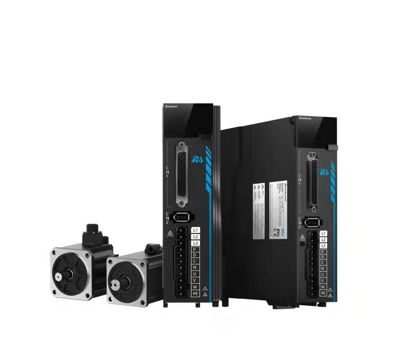
2.1.1 driver mode descripition 7
2.1.2 servo driver structure 8
2.2 Adaptation of Servo Drivers and Motors 9
2.3 Dimensions of the Drive 10
2.4 Motor Product Information 11
2.4.1 Motor model and nameplate description 11
3 Installation and Wiring 13
3.1 Installation and Dimensions 13
3.1.1 Installation Environment 13
3.1.2 Installation direction and installation space 14
3.1.3 External dimensions of servo motor 15
3.1.4 Technical specifications of servo motor 18
3.2 Definition of Wiring and Terminals 19
3.2.1 0.4KW~1.5KWservo driver wiring 19
3.2.2 2.6~3KWservo driver wiring 21
3.2.3 Definition of Command Terminal CN1 25
3.2.4 Confirmation of Input Signal Status 33
3.3 Selection Instructions for Braking Resistors 34
3.3.1 Operating condition description of braking resistor 34
3.3.2 Braking Resistance Calculation 35
4 Panel Display and button Operation 39
4.1 Panel Composition 39
4.2 Menu Structure 40
4.3 Common servo panel displays 41
4.4 Monitoring Display 42
4.5 Auxiliary Function Parameters (Fun Group Parameters) 42
4.5.1 F-000 servo re-start 42
4.5.2 F-001 Alarm clear 44
4.5.3 F-002 JOG enable 46
4.5.4 F-003 Inertia Identification 47
4.6User passwords 49
5 Operation and Debugging 51
5.1 Instructions for Using Position Mode 51
5.1.1 Position Mode Wiring 52
5.1.2 Function code settings related to position control mode 53
5.2 Instructions for Using Speed Mode 60
5.2.1 Speed mode wiring: 61
5.2.2 Speed mode related function code settings 62
5.3 Instructions for Using Torque Mode 68
5.3.1 Torque Mode Wiring 69
5.3.2Torque Mode Related Function Code Setting 70
5.4 Mixed Control Mode 78
5.5 Absolute Value System Instructions 81
5.5.1 Overview 81
5.5.2Relevant Function Code Settings 81
5.6 Trial Operation 86
5.6.1 Inspection and Precautions Before Trial Operation 86
5.7 Adjustment 87
5.7.1 Safety precautions during adjustment 87
5.7.2 Basic Process of Adjustment 88
5.7.3 Safety precautions during adjustment 89
5.7.4 Single parameter adjustment 89
5.7.5 Manual Adjustment Function 91
5.7.6 Feedforward gain 93
5.7.7 Mechanical vibration suppression 94
5.8 Virtual VDI/VDO 96
5.8.1 Virtual Digital Signal Input Terminal (VDI) 96
5.8.2 Virtual Digital Signal Output Terminal (VDI) 98
5.9 Instructions for using multi-stage position mode 99
5.10 Instructions for using multi-stage speed mode 102
5.11 Driver Matching Instructions for Non HK Series Motors 105
5.11.1 Parameter Settings Before Pairing 105
5.11.2 Motor zeroing operation after parameter setting 107
5.12 Brake Setting 109
5.12.1 Brake Wiring 109
5.12.2 Brake software settings 110
5.12.3 Brake problem 110
5.12.4 Troubleshooting of Brake Problems 114
5.13 Origin Return Function 115
5.13.1 Origin Return to Zero (Motion Return to Zero) 116
5.13.2 Using the current position as the origin 120
5.13.3 Origin and Zero Point 120
5.13.4 Examples of Use 121
6 Fault troubleshooting 125
6.1 Troubleshooting before Operation 125
6.2 Troubleshooting during runtime 126
6.2.1 Troubleshooting Operation 126
6.2.2 Troubleshooting for inaccurate positioning 128
6.3 Software Alarm 131
6.3.1 Alarm Categories and Display 131
6.3.2 Alarm Record 134
6.3.3 Software Alarm troubleshooting Methods 135
7 Modbus communication 153
7.1 Hardware Wiring and Parameter Configuration 153
7.2 Modbus Communication Protocol 153
8 User Parameters 162
8.1 P00 Servo Basic Parameter Group 163
8.2 P01 IO input Parameter Group 167
8.3 P02 IO Output Parameter Group 174
8.4 P03 Gain Adjustment Parameter Group 178
8.5 P05 Position Control Parameter Group 182
8.6 P06 Speed Control Parameter Group 193
8.7 P07 Torque Control Parameter Group 194
8.8 P08 Analog Parameter Group 197
8.9 P09 Communication Control Parameter Group 198
8.10 P0A Shutdown Control Parameter Group 203
8.11 P0B Fault and Protection Parameter Group 205
8.12 P0C multi-stage position control parameter group 208
8.13 P0D multi-stage speed control parameter 209
8.14 P0E adaptive adjustment parameter group 212
8.15 P10 motor parameter group 216
8.16 P11 Driver Parameter Group 220
8.17 P12 Auxiliary Function Parameter Group 225
8.18 P13 Monitoring Parameter Group 226
8.19 P15 Virtual IO Parameter Group 232
8.20 P16 version information parameter group 240
9 Appendix Version Modify description 241