1. Connection of ladder diagram components
1. Connection of ladder diagram components
The ladder diagram connects instructions through connecting lines, which are divided into horizontal and vertical directions. By connecting the energy output of one instruction to the energy input of another instruction, program logic is formed between the instructions.。
1.1. Serial logic
Multiple instructions are connected in series by horizontal connection lines, and the energy flow to the left of each instruction determines whether the instruction is executed.

图1 Concatenated
The last instruction must end in a coil or rectangle, otherwise it will result in an open circuit error.
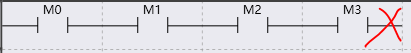
图2 Circuit Breaker
1.2. Parallel logic
The instructions and serial logic are connected by vertical connection lines at the beginning and end, sharing the input of energy flow, and the output of energy flow takes the OR operation of these logics.
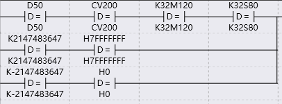
图3 Parallel
If one of the groups is only composed of horizontal connecting wires, it causes a short circuit error.
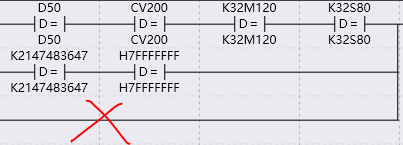
图4 Short Circuit
1.3. Branch Logic
Multiple output logics share a common conditional logic at the beginning, connected by vertical connection lines.
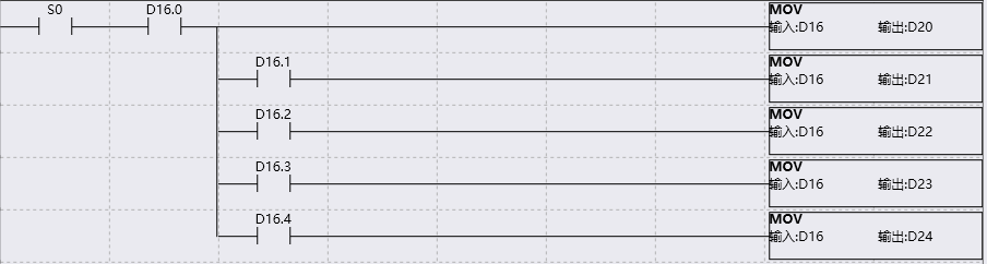
图5 Branch
If one of the output logics is connected forward to the leftmost bifurcation point and there is also a left instruction connected, it causes a mixed connection error.
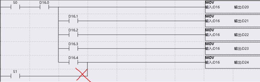
图6 Mixed Connection
If it is connected from the left side forward to the leftmost side, there is no problem. Please make a distinction.
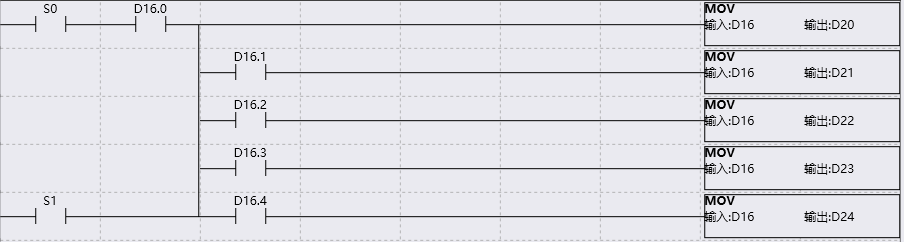
图7 Legitimate Branch