1. Function Block Diagram Editor
1. Function Block Diagram Editor
our software Function Block Diagram (FBD) editor allows you to view instructions in the form of logical boxes (similar to general logic gate diagrams). There are no contacts and coils in the LAD editor in FBD, but there are equivalent instructions displayed in the form of box instructions. The program logic is derived from the connections between these box instructions. The output from one instruction (such as the AND box) can be used to enable another instruction (such as a timer) to create the necessary control logic. This connection concept allows you to easily solve various logical problems just like using other editors.
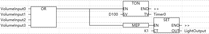
图1 FBD editor
If the box has energy flow at the EN input and performs without errors, the ENO output will pass the energy flow to the next element. ENO can be used as an enable bit to indicate successful completion of the instruction. The ENO bit is used at the top of the stack to affect the energy flow used for subsequent instruction execution.
1.1. Key points
The key points to consider when choosing an FBD editor include:
The graphical logic gate representation style is beneficial for following program flow.
Programs created using the FBD editor can be displayed using either the LAD editor (Lad. html) or the STL editor (Stl. html).
Expandable AND/OR boxes facilitate the drawing of complex input combinations.