1. Ladder diagram editor
1. Ladder diagram editor
our software Ladder Diagram (LAD) Editor allows you to create programs similar to electronic circuit diagrams. Ladder diagram programming is a method chosen by many PLC programmers and maintenance personnel; It is an excellent language designed for new programmers. Basically, ladder diagram programs allow the CPU to simulate current from a power source, through a series of logical input conditions, and then enable logical output conditions. Logical decomposition into program segments. The program executes according to instructions, one program segment at a time, in order from left to right, and then from top to bottom. Once the CPU reaches the end of the program, it returns to the top of the program to restart.
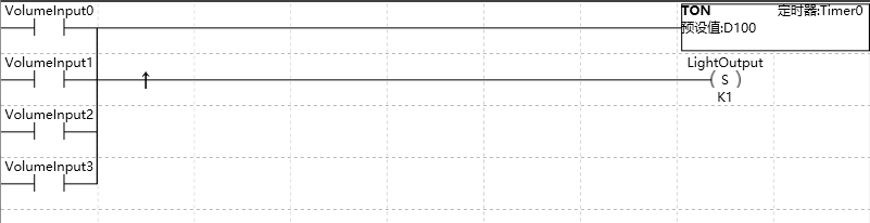
图1 LAD editor
Various instructions are represented by graphical symbols, including three basic forms.
| Graphic | Name | Description | |
|---|---|---|---|
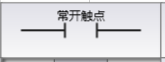 |
Input Contacts | Represents logical input conditions, used to simulate switches, buttons, internal conditions, etc. The normally open contact of the image is a type of input contact. | |
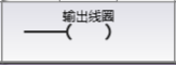 |
output coil | Usually represents the logical output result, used to simulate lights, motor starters, intervention relays, internal output conditions, and other outputs. | |
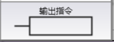 |
output command | Represents additional instructions, such as timers, counters, or mathematical instructions. |
Box shaped output instructions cannot be concatenated,onlyFBD can concatenate output instructions.
1.1. key point
选择 LAD 编辑器时要考虑的要点包括:
The key points to consider when choosing an LAD editor include:
Trapezoidal logic is convenient for new programmers to use.
Graphic displays are usually easy to understand and widely used worldwide.
Programs created using the LAD editor can always be displayed using either the FBD editor (Fbb. html) or the STL editor (Stl. html).