Troubleshooting during runtime
Troubleshooting of Operational Malfunctions
Servo enabled state will displayed as "ru" on the tube,and if the servo has not entered the enabled state, please follow the method of "1.1 Troubleshooting before Operation" for troubleshooting.
After inputting the command, the servo did not run as expected or ran unevenly. Please follow the suggestions in the table below for troubleshooting.
Fault phenomenon | Fault reason | Handling methods |
When inputting commands, the motor does not rotate | 1. Wiring error | Please refer to Chapter 3 "Wiring" to ensure that the command pulse signal line is correctly connected, the enable switch, and the overtravel switch are correctly connected |
2.Servo parameter configuration error | Location operation mode 1. Ensure that the "P5-15 position command source" is consistent with the actual input position command method 2. Ensure that the "P5-16 instruction pulse shape" is consistent with the actual input instruction pulse signal shape (when inputting the AB signal, the incorrect configuration is "[0] pulse+direction", and the pulse count will be very small) 3. Ensure that the "P5-00 Single Cycle Pulse Number" is set correctly. When the value of the single cycle pulse number is large, the actual rotation of the motor is very small after inputting the command pulse Speed operation mode 1. Ensure that the command source set for "P6-00 Speed Command Selection" matches the actual input command When selecting analog input commands, check whether the AI analog input channel selection is correct ("P6-01 speed command A source", "P6-02 speed command B source"), and check whether the AI terminal wiring is correct When the number is given, check if the "P6-03 speed command digital setting value" is correct When the jog speed command is given, check whether the "P6-04 jog speed setting value" is correct, check whether the P01 group has set the DI function "[18] forward jog" and "[19] reverse jog", and whether the corresponding terminal logic is valid 2. Check if the "P6-05 Speed Command Acceleration Time" and "P6-06 Speed Command Deceleration Time" settings are correct Torque operation mode Ensure that the command source set for "P7-00 torque command source" matches the actual input command When selecting analog input commands, check whether the AI analog input channel selection is correct ("P7-01 torque command A source", "P7-02 torque command B source"), and check whether the AI terminal wiring is correct When the number is given, check if the "P7-03 torque command digital setting value" is correct | |
3.The input command has not taken effect |
| |
When inputting command, the motor rotates in the wrong direction | Parameter configuration error | Location operation mode 1. Check if the "P02-02 Motor Rotation forward Direction Definition" is set correctly 2. Check if the "P05-17 instruction pulse signal inversion" setting corresponds to the actual input pulse polarity, and verify if the terminal wiring is correct 3. Check if the DI function "[27] Position Command Direction" has been set and if the corresponding terminal logic is valid Speed operation mode 1. Check if the "P02-02 Motor Rotation forward Direction Definition" is set correctly 2. When selecting analog input commands, check if the polarity of the input signal is reversed 3. When the value is given, check if the "P6-03 speed command digital setting value" is correct 4. Check if the DI function "[26] Speed Command Direction" has been set and if the corresponding terminal logic is valid 5. When the jog speed command is given, check whether the "P6-04 jog speed setting value" is correct, check whether the P01 group has set the DI function "[18] forward jog" and "[19] reverse jog", and whether the corresponding terminal logic is valid Torque operation mode 1.Check if the "P02-02 Motor Rotation forward Direction Definition" is set correctly 2.When selecting analog input commands, check if the polarity of the input signal is reversed Check if the DI function "[25] Torque Command Direction" has been set and if the corresponding terminal logic is valid |
1、Unstable speed during low-speed operation 2、Vibration occurs during running | 1、Unreasonable gain setting | 1. Adjust the rigidity level (when the value of "P3-00 self-tuning mode selection" is not "[0] manually adjust the gain parameter", adjust "P3-01 rigidity level") 2. Perform gain adjustment. When the value of "P3-00 self-tuning mode selection" is set to "[0] manual adjustment of gain parameter", adjust parameters such as "P3-04 position loop gain", "P3-05 speed loop gain", "P3-06 speed loop integration time constant", etc Unstable during low-speed operation, try increasing the rigidity level Vibration during operation, try to reduce the rigidity level |
2、“P03-02 load moment of inertia ratio mismatch |
| |
Inaccurate positioning | Refer to the next section "7.2.2 Troubleshooting for inaccurate positioning" for handling | |
Inaccurate positioning investigation
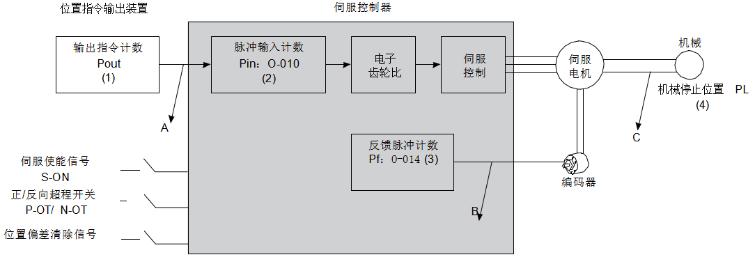
Figure 6-1 Servo positioning control process
Inaccurate positioning occurred, check the 4 signals in the above picture
(1) The output command count Pout (internal parameter of the controller)
(2) The input position command counter Pin received by the servo controller corresponds to the parameter "O-010 pulse command count"
(3) The feedback pulse accumulation value Pf of the servo motor's built-in encoder corresponds to the parameter "O-014 Feedback Pulse Count"
(4) Mechanical stop position PL
In an ideal state where no positional deviation occurs, the following relationship holds:
● Pout = Pin
● Pf = Pin × Electronic gear ratio
● PL = Pf × ∆L,that ∆L is: 1 position instruction corresponds to load displacement
Follow the method shown in the table below to troubleshoot the problem one by one
phenomenon | |
Reason for malfunction |
|
Troubleshooting methods |
|
Encoder feedback position signal error (signal interference) |
|
Mechanical position sliding occurred between the machine and servo motor |
Step by step check the connection status of the machinery and identify the location where relative sliding occurred |