1. Project setting
1. Project setting
Click on "Settings" in the menu, select "Project Settings" in the settings bar, and choose "Settings"; Engineering Settings "will open the PLC's engineering settings.
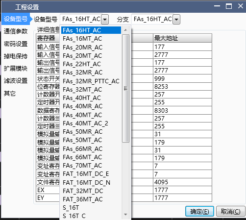
1.1. 1. PLC mode setting
Hereby our CPU mode and expansion mode:
CPU-16HT-AC, CPU-16MT-AC, CPU-20MR-AC, CPU-20MT-AC, CPU-22HT-AC
,CPU-32MR-AC, CPU-32MT-AC, CPU-40HT-AC
,CPU-40MR-AC, CPU-40MT-AC, CPU-50MR-AC, CPU-50MT-AC
, CPU-66MR-AC, CPU-66MT-AC, CPU-70MT-AC, CPU-16MT-DC-E
, CPU-16MT-DC-N, CPU-32MT-DC, CPU-36MT-AC
Expansion module:
Expansion module-16-T, Expansion module-16T-C, Expansion module-16T-M, Expansion module-8X8T, Expansion module-8X8T-C, Expansion module-8X8T-M, Expansion module-E12R
,Expansion module-E16T, Expansion module-E16X, Expansion module-E16X-C, Expansion module-E4AI2AO, Expansion module-E4AI4T, Expansion module-E4PT4T, Expansion module-E4TC4T,Expansion module-E8X8R, Expansion module-E8X8T
Attention:
If the user cannot distinguish the actual model of the PLC currently connected, they can also choose any one when creating a new project, because there will be a model verification function during download to help the user automatically switch models;
Different models may have different functions, and some commands can only be used in a certain model;
1.2. 2. Communication parameter settings
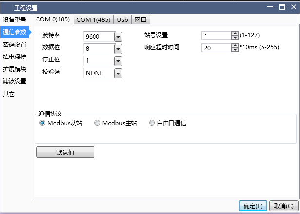
COM port parameter settings: On this page, corresponding settings can be made for the communication parameters of the PLC. The default communication parameters for PLC serial port are: baud rate 9600, data bit 8, stop bit 1, and checksum NONE;
Serial communication protocol types: including Modbus master, Modbus slave, and free port communication. The default protocol is Modbus slave;
Station number: Set the station number of the PLC, and different COM ports can have different station numbers;
Timeout: This parameter only takes effect during Modbus master communication and has no practical significance for slave and free port communication. It represents the maximum waiting time for the PLC to receive one packet of data from the slave each time it communicates as the master, with a default value of 20 * 10ms;
Number of retransmissions: This parameter only takes effect during Modbus master communication and has no practical significance for slave and free port communication. It represents the number of retransmissions that will occur again when receiving data from the slave after timeout, with a default value of 3;
Buffer bit: This parameter only takes effect during free port communication and has no practical significance for Modbus master and slave stations. It indicates whether data is buffered in 8-bit or 16 bit format during communication;
Attention:
If you want to use MODBUS master communication, you must select the Modbus master protocol, establish and edit a Modbus master table, and use Modbus commands in the ladder diagram;
When the communication protocol of the COM port is set to MODBUS master or free port communication, it can no longer be used to download projects, nor can it be monitored. Only when the Modbus slave protocol is selected and downloaded to the PLC can it have download and monitoring functions;
In addition to downloading and updating serial port information through configuration information, settings for serial port baud rate, data bits, stop bits, checksum, station number, etc. can also be set through special registers D8066~D8075, M8176~M8183;
1.3. 3. password setting
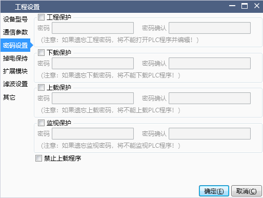
Engineering protection: Set the engineering protection password for the PLC program. When opening the project, it will prompt for a password change. Forgetting to change the password will cause the program to fail to open
Download protection: Set the download password for the PLC program. When downloading the program, you will be prompted to enter the password. Forgetting the password will result in the inability to update the internal program of the PLC
Upload protection: Set the upload password for the PLC program. When uploading the program, you will be prompted to enter the password. Forgetting the password will cause the program to fail to upload
Monitoring protection: Set the password for PLC monitoring, which will be used when monitoring this mode on the upper ladder diagram. Forgetting this password will prevent monitoring the PLC program
Prohibit program upload: Check the option to prohibit program upload, and you will be prompted that the program cannot be uploaded when uploading
Note: Passwords must start with a letter or number and be between 4 and 12 digits in length.
1.4. 4. Power outage hold zone setting
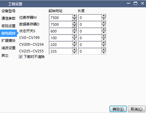
On this page, you can set the capacity of the power-off hold area. When you click on the default settings, the current settings will be cleared and the starting address of the power-off hold area will be set to the minimum value, and the length will be set to the value shown in the image.
When selecting download, do not clear the power-off hold data. When downloading the ladder diagram program, the data in the power-off hold area before downloading will not be cleared.
The power down hold function is not affected by the 'Do not clear during download' setting and always executes according to the user's set table.
1.5. 5. Expansion module settings
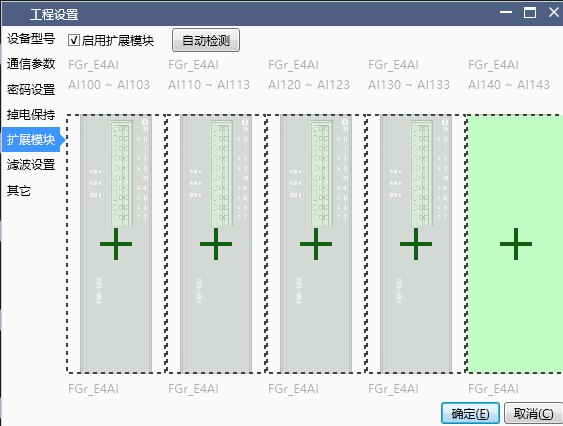
Check the option to use the extension module and start setting up the extension module.
For specific usage, please refer to theExtension Module User Manual。
1.6. 6. Filter setting
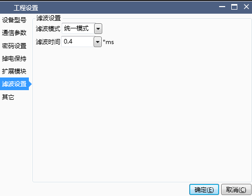
- There are three modes for filter settings: not enabled, unified mode, and other modes
When not enabled, software filtering of input signal X will not be enabled;
When the unified mode is selected, the filtering time can be configured, and the filtering parameters are applicable to all X input channels;
When selecting other options, the filtering time for each X input channel can be configured separately;
1.7. 7. others
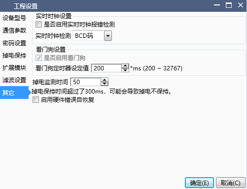
Real time clock settings:
The real-time clock can be configured to read and write in BCD code or decimal format;
When real-time clock error detection is enabled, if the real-time clock is abnormal, the PLC will enter the ERROR or STOP state, and the PLC will stop running. You can check whether D8176 is equal to 9 or monitor the status bar information through the upper software;
When real-time clock error detection is not enabled, even if the real-time clock is abnormal, it will not affect the normal operation of the PLC. It is still possible to check whether the PLC is abnormal through D8176 or the monitoring information status bar;
Watchdog settings:
The watchdog timer value can be set, which is generally used to detect the problem of dead loops caused by users writing ladder diagrams or function blocks;
At the end of each scanning cycle of PLC operation, the watchdog will be reset internally by default, or it can be manually reset by using the WDT instruction in the ladder program;
If there is no reset after exceeding the set value time, the PLC will enter the ERROR or STOP state, and the PLC will stop running. You can check whether D8176 is equal to 10 or monitor the status bar information through the upper software;
Setting of power outage hold time:
This parameter is used to set the PLC to determine the filtering time of the PLC power-off software. If it is set to the default value of 50ms, it indicates that the power grid fluctuation is below 50ms, and the PLC is considered to be in a normal power supply state. If it exceeds 50ms, the PLC is considered to have entered a power-off state, and the PLC will stop running and store power-off maintenance data;
When external interference is severe and causes the PLC to enter the STOP power-off state during operation, the power-off detection time can be appropriately increased;
When increasing this value, it may affect the normal storage of power-off data, causing the power-off data to not be maintained. Therefore, the power-off detection time should only be slightly increased appropriately when the external power supply voltage is unstable and the PLC may mistakenly enter the power-off mode. In other cases, please do not modify this parameter value without authorization;