1. Logical elements and working principles of functional block diagrams
1. Logical elements and working principles of functional block diagrams
1.1. Elements
The software Function Block Diagram (FBD) editor allows you to view instructions in the form of logical boxes (similar to general logic gate diagrams):

图1 button
You can use the AND button (or shortcut key F2) to insert the AND command.

图2 And instruction

图3 Button
You can use the OR button (or shortcut key F3) to insert the OR command.

图4 Or instruction
You can double-click the cell box in the editor (or select the cell box and press enter) to open the指令选择器。
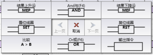
图5 instruction selector
You can select the unit box in the editor and enter instructions to open theinstruction input box。
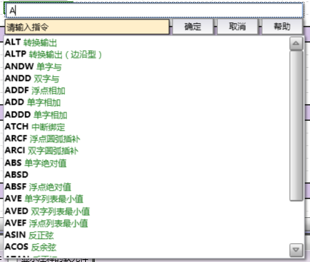
图6 instruction input box
The program logic is derived from the connections between these box instructions. That is, the output from one instruction (such as the AND box) can be used to enable another instruction (such as self add) to create the necessary control logic.
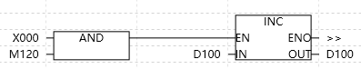
图7 Program logic
1.2. Related steps
The input and output of FBD instructions can be modified in the following ways:
Boolean (bit value) input can be inverted to create a logical condition for inversion (input becomes normally closed/ON instead of normally open/OFF).
Boolean (bit value) input or output can be converted to immediate input/output, so that the address is updated immediately instead of updating at fixed intervals during the program's periodic scanning cycle.
It is possible to take rising/falling edge signals for Boolean (bit value) inputs, creating a condition for taking edge signals (only becoming ON during one scan cycle of OFF → ON or ON → OFF).
If necessary for program logic, additional inputs can also be added to AND or OR instructions. If you change your mind, you can also remove the additional input and return the command to the default values of the two inputs.