3.2 Electrical wiring
After opening the terminal sliding cover, expose the wiring terminal block and check if the terminals of each main circuit and control circuit are clearly indicated. Pay attention to the following instructions when wiring:
1. The R/L1, S/L2, and T/L3 are the input power terminals. If the power supply is incorrectly connected to other terminals, it will damage the frequency converter. Additionally, it should be confirmed that the power supply should be within the allowable voltage/current range indicated on the nameplate.
2. The grounding terminal must be well grounded, which can prevent electric shock or fire accidents and reduce noise interference。
3. Please ensure that the screws connecting the terminals and wires are locked tightly to prevent vibration loosening and sparks.
4. Wiring when power on is prohibited.
| 1. Before wiring, please confirm that the input power has been cut off. There is a risk of electric shock and fire. 2. Please let electrical engineering technicians perform wiring operations. 3. he grounding terminal must be reliably grounded. 4. After the emergency stop button is turned on, be sure to check if its action is effective. (Wiring responsibility is borne by the user) 5. Do not touch the terminals directly, do not connect the terminals of the frequency converter to the shell, and do not short circuit between the terminals. There is a risk of electric shock and short circuit。 |
|---|---|
| 1. Please confirm if the rated voltage of the AC power supply and the frequency converter are consistent. There is a risk of injury and fire.。 2. Do not perform voltage withstand tests on the frequency converter. Will cause damage to the internal semiconductor components of the frequency converter.。 3. Please connect the braking resistor or braking unit according to the wiring diagram. 4. Please tighten the terminals with a screwdriver of the specified torque. 5. Do not connect the input power cable to the U, V, W terminals. That can cause internal damage to the frequency converter.。 6. Do not connect phase-shifting capacitors and LC/RC noise filters to the output circuit. Will cause internal damage to the frequency converter。 7. Do not connect any switches or contactors to the output circuit. When the frequency converter operates under load, the action of switches and contactors will generate surge current and surge voltage, leading to damage to the frequency converter. 8. Do not disassemble the internal connection cables of the frequency converter. May cause damage to the frequency converter |


3.2.1 Connection configuration of peripheral devices
The connection diagram between SK300 series frequency converters and peripheral devices is shown in image 3-8;
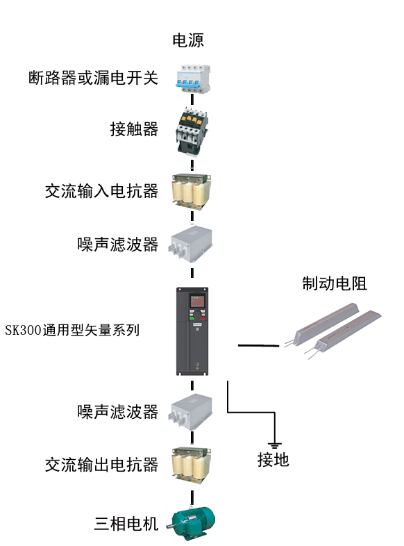
image 3-8 SK300 wiring method
3.2.2 Schematic diagram of main circuit terminal and control circuit terminal wiring
The standard wiring for the main circuit and control circuit of the SK300 series frequency converter is shown in image 3-9:
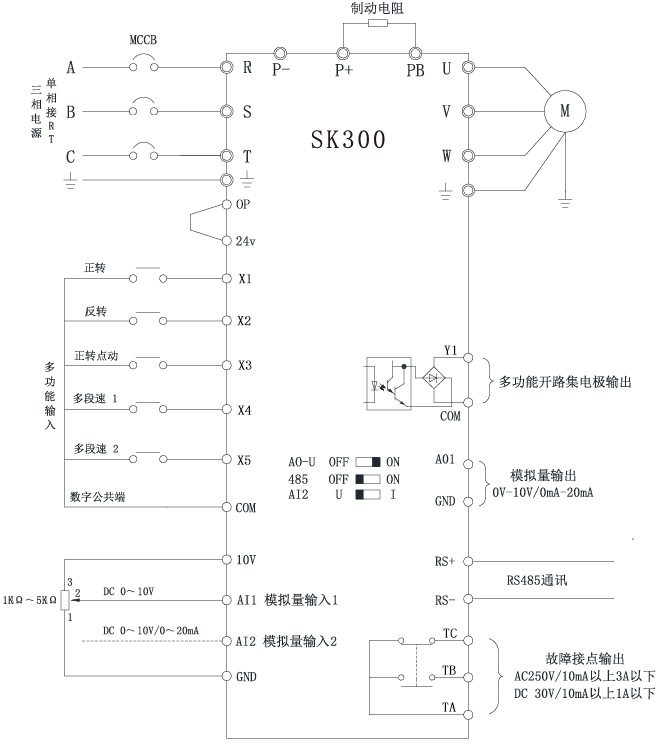
image 3-9 Standard wiring for main and control circuits

●If the load connected to the multifunctional output terminal is an inductive load (such as a relay coil), it is necessary to parallel freewheeling diodes at both ends of the load.
●The control cable inside the frequency converter or control cabinet should
be at least 100mm away from the power cable and should not be placed in the same wire duct; If the signal cable must pass through the power cable, the two should be orthogonal (90°angle). The control cable must use shielded twisted pair cables, and the GND of the shielding layer terminals should be connected. It is best to use power shielded cables also.
● Due to the inevitable presence of strong electromagnetic interference in frequency converters, it can have adverse effects on various electrical equipment and instruments located in the same environment. To suppress interference, the output cable of the frequency converter can be sheathed in a grounded metal pipeline, or an armored shielded cable can be used, and the armored shielding layer can be grounded. In addition, adding a magnetic ring on the output cable can effectively suppress interference。
3.2.3 The function of the main circuit terminal
The main circuit terminals of SK300 series frequency converters are shown in the following figures
R | S | T | P+ | P- | PB | U | V | W | PE |
|---|---|---|---|---|---|---|---|---|---|
POWER | MOTOR | ||||||||
SK300 0.75KW-2.2KW Main circuit terminal diagram
R | S | T | P+ | P- | PB | U | V | W | PE |
|---|---|---|---|---|---|---|---|---|---|
POWER | MOTOR | ||||||||
SK300 4.0KW-5.5KW Main circuit terminal diagram
Teminal mark | Function description |
|---|---|
R、S、T | AC power input terminal, three-phase R/S/T Or single-phase to R/T |
U、V、W | The output terminal of the frequency converter is connected to a three-phase AC asynchronous motor. |
P+、P- | Connect the positive and negative terminals of the DC bus |
PB | External braking resistor connection terminal, with one end connected to P+and the other end connected to PB. |
PE | Ground connection |
● It is strictly prohibited to connect terminals other than R, S, and T in the control terminals to an AC 380V power supply, otherwise there is a risk of damaging the frequency converter.
● Verify whether the rated input voltage of VFD is consistent with the voltage of the AC power supply. If the input voltage level is inconsistent, it may cause damage to the frequency converter.
● Be sure to connect the grounding terminal of VFD and the motor shell to the grounding wire. The grounding wire should use copper core wire with a cross-sectional area of 4cm ² or more, and the grounding resistance must be less than 10 Ω
● A fuse free circuit breaker must be connected between the power supply and the VFD to prevent accidents caused by frequency converter faults from expanding, damaging the power supply device, or causing fires.
3.2.4 Main circuit wiring
The main circuit wiring of SK300 series frequency converters is shown in image 3-10
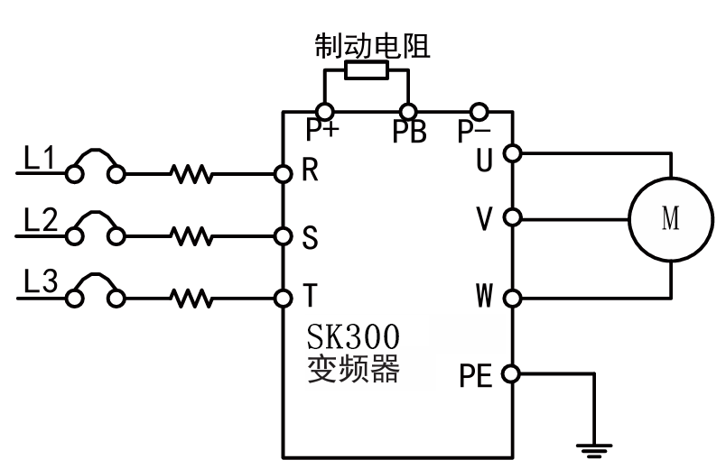
image 3-10
3.2.5 Main circuit input side wiring
◆ Circuit breaker installation
Please be sure to install the corresponding air circuit breaker (MCCB) for the VFD between the power supply and input terminals.
Please select the capacity of MCCB as 1.5-2 times the rated current of the VFD.
The time characteristics of MCCB should meet the time of the VFD overheating protection (150% rated current/1 minute).
When MCCB is shared with multiple VFD or other devices, please connect the fault relay output of the VFD in series with the power contactor coil, as shown in Figure 3-11, when receive fault signal can disconnect the power supply.
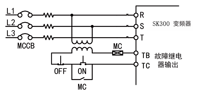
image 3-11
◆ Installation of leakage switch
As the output of the frequency converter is a high-frequency PWM signal, it will generate high-frequency leakage current. Please choose a frequency converter specific leakage circuit breaker with a current sensitivity of 30mA or above; If using a regular leakage circuit breaker, please choose a leakage circuit breaker with a current sensitivity of 200mA or above and an operating time of 0.1 seconds or more
◆ Installation of electromagnetic contactors
Connect the electromagnetic contactor that matches the power of the frequency converter as shown in Figure 3-11. Do not frequently use the incoming electromagnetic contactor to control the operation and stop of the frequency converter. Frequent use of this method is an important cause of damage to the frequency converter. If it is necessary to use the incoming electromagnetic contactor for control, the frequency of operation for running and stopping should not be less than 30 minutes per time.
◆ Installation of AC reactor
When the input power is connected to a capacitive load, a large surge current will be generated, which may damage the frequency converter. If this situation occurs, please connect a three-phase/single-phase AC reactor (optional) on the input side of the frequency converter. This not only suppresses peak currents and voltages, but also improves the power factor of the system.
◆ Installation of noise filter
To suppress power grid side noise entering the frequency converter and suppress the impact of noise generated by the frequency converter on the power grid. The frequency converter requires the use of dedicated noise filters, while ordinary noise filters have poor performance and are generally not used. The correct and incorrect installation methods for noise filters are shown in Images 3-12 and 3-13.
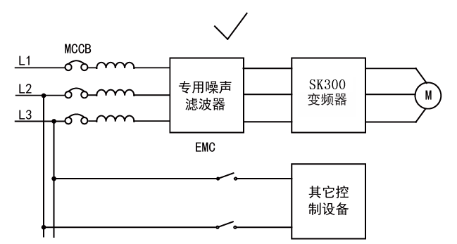
image 3-12 filter correct
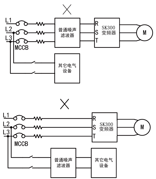
image 3-13 filter incorrect
3.2.6 Main circuit output side wiring
◆ Motor wiring installation
For VFD ,simply connect the output terminals U, V, W to the input terminals U, V, W of the motor. During operation, please confirm whether the motor is rotating forward during the forward command. If it is necessary to change the direction of the motor, swap any two wires of the output terminals U, V,W of VFD
◆ Do not connect the power input to the output terminal
Do not connect the power to the output terminal,that will damage the internal components of the VFD.
◆ prohibited to short circuit or ground the output terminals
Do not directly touch the output terminals or short-circuit the output wiring to the VFD shell, otherwise there is a risk of electric shock and short circuit. Also, do not short-circuit the output line.。
◆ Prohibit the use of phase-shifting capacitors
Do not connect phase-shift electrolytic capacitors or LC/RC filters in the output circuit, otherwise it will damage the VFD.
◆ Prohibit the use of electromagnetic switches
Do not connect electromagnetic switches or contactors in the output circuit. Otherwise, the operation of such devices will cause over current and over voltage protection actions, and in severe cases, it may even damage the internal components of the frequency converter.
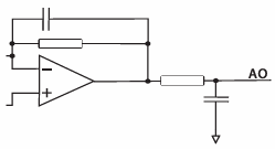
◆ Installation of noise filter
Connecting a noise filter on the output side of the frequency converter can reduce induced interference and radio interference. Inductive interference: Electromagnetic induction causes noise on the signal line, cause to misoperation of control equipment.。
Radio interference:
The high-frequency electromagnetic waves emitted by the frequency converter itself and cables can interfere with nearby equipment, causing noise during signal reception. Install a noise filter as shown in image 3-14
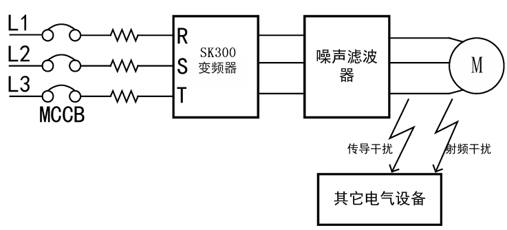
image 3-14 wiring of output side noise filter
◆ Example of anti-interference installation
To suppress interference on the output side, except installing a noise filter as mentioned earlier, grounded metal tube can also be used. The distance between the output cable and the signal cable is greater than 30cm, interference will significantly reduced; Input and output connections, as well as the VFD itself, can generate radio frequency interference. Installing noise filters on both sides of the input and output, and shielding the frequency converter body with an iron box, can reduce radio frequency interference, as shown in image 3-15. When multiple VFD are used simultaneously, grounding method shown in image 3-16.
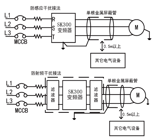
image 3-15 Anti interference wiring
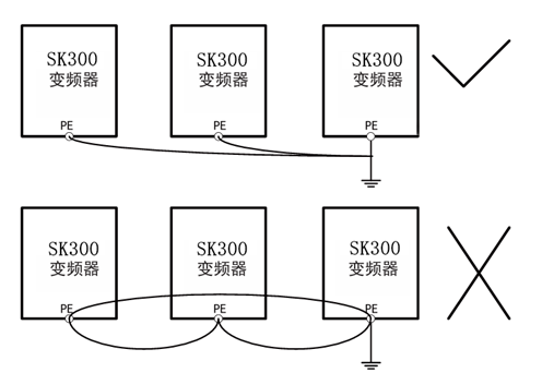
image 3-16 ground
3.2.7 Function of control circuit terminals
The control circuit terminals of SK300 series frequency converters are shown in the following image
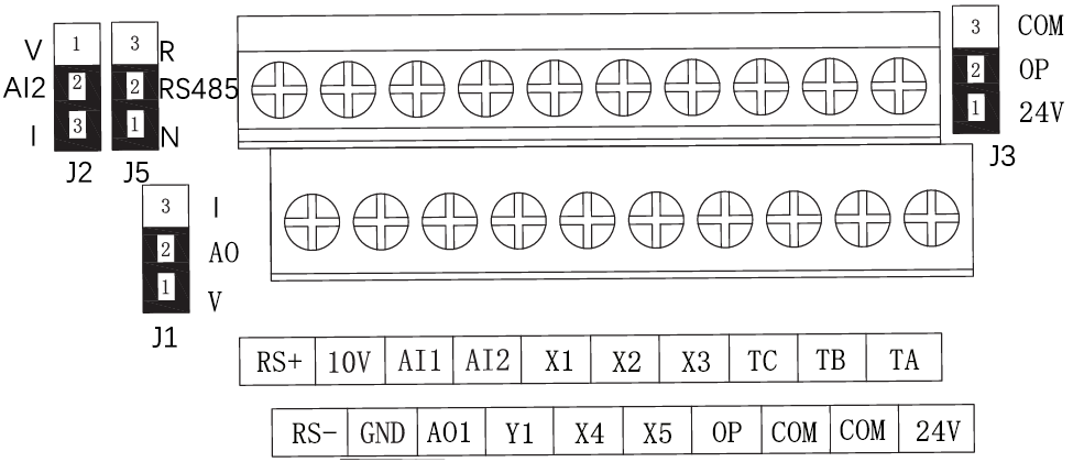
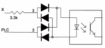
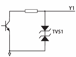
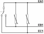
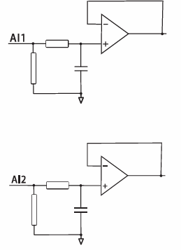
image 3-17 control circuit terminal
Function Description of Control Circuit Terminals:
Category | Terminal Number | Function Description | Electrical Specifications | Internal Circuits |
|---|---|---|---|---|
Digital input terminals | X1 | VFD could be programmed with function codes, as start,stop,forward or reverse rotation. | Input impedance:3.3K Input voltage:0~24V Input frequency:<1KHz Default low-level active |
|
X2 | ||||
X3 | ||||
X4 | ||||
X5 | ||||
Digital output terminal | Y1 | Programmable digital output | Open collector output |
|
TA/TB/TC | Programmable relay output | TA is the common terminal of normally open and closed |
| |
Analog input | AI1 | 0~10V input | voltage:0~10V impedance:1M |
|
AI2 | 0~10V/0~20mA input | current:0~20mA impedance:250Ω | ||
Analog output | AO1 | Programmable analog output | voltage:0~10V current:0~20mA |
|
RA485 com | RS+/RS- | RS485 port | ||
10V power | 10V | 10V External power | 10mA | |
24V power | 24V | 24V External power | 150mA |