3.1 Mechanical Installation
3.1.1 Installation environment requirements
The operating temperature range of the frequency converter is -10 ℃ to 40 ℃. When the ambient temperature is above 40 ℃, a fan should be added to enhance ventilation, for every 5 ℃ increase when over 40℃, the rated power of VFD should be reduced by 10%
3.1.2 Installation site
◆ Places without corrosive, flammable and explosive gases and liquids;
◆ The humidity at the installation site is below 90%, and there is no condensation of water droplets;
◆ Installed in places with vibration less than 5.9m/s2 (0.6g);
◆ Do not install in dusty or metal powder areas;
If the user has special installation requirements, please consult the manufacturer in advance and confirm.
3.1.3 Installation precautions
During installation work, please take effective protective measures for the frequency converter to prevent metal fragments or dust generated by drilling from falling into the interior of the frequency converter. After installation, please remove the protective equipment.
3.1.4 Installation interval and heat dissipation
The installation method of the frequency converter is wall mounted. The installation interval and distance requirements for a single frequency converter are shown in Figure 3-1,When two frequency converters are installed up and down, a guide baffle should be used in the middle, as shown in Figure 3-2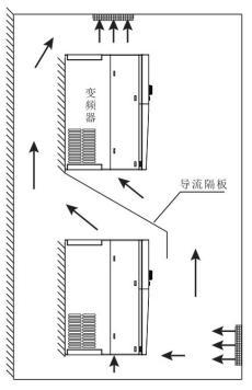
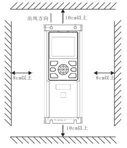
image 3-1 interval image 3-2 two VFD


◆ The higher the ambient temperature, the shorter the life of the frequency converter。
◆ If there is a heating device near the frequency converter, please move it as far away as possible. In addition, when the frequency converter is installed inside the box,take consideration of space size, which is beneficial for heat dissipation.
3.1.5 Screw installation method
Our VFD adopts a diagonal two hole installation method, and the installation hole size refers to the external and installation dimensions of the product. Drill two holes on the installation surface, and then install and tighten the screws from the holes. As shown in image 3-3。
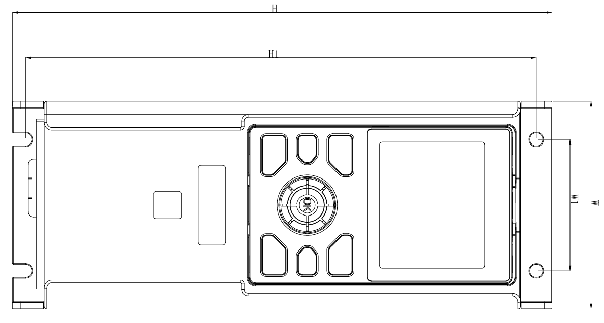
image 3-3 Screw installation method
3.1.6 Removing and installing the keyboard
A. Disassemble the keyboard, as shown in image 3-4: First press the keyboard elastic buckle in direction 1, and then lift the keyboard in direction 2.
B. Install the keyboard, as shown in image 3-5: Place the keyboard flush into the keyboard slot, press the keyboard in direction 1 until you hear a "click" sound that is flush with the front surface of the VFD.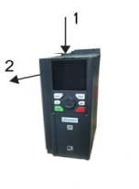
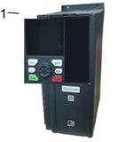
image 3-4 Disassemble image 3-5 install
3.1.7 Disassembly and installation of terminal cover
A.Remove the terminal cover, as shown in image 3-6. Press the terminal cover in direction 1 and then remove it in direction
B.Install the terminal cover, as shown in image 3-7. In direction 1, install the upper buckle of the terminal cover into the corresponding joint of the upper shell until a "click" sound is heard at the joint。
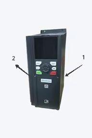
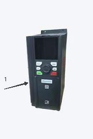
image 3-6 remove image 3-7 install