Definition of Wiring and Terminals
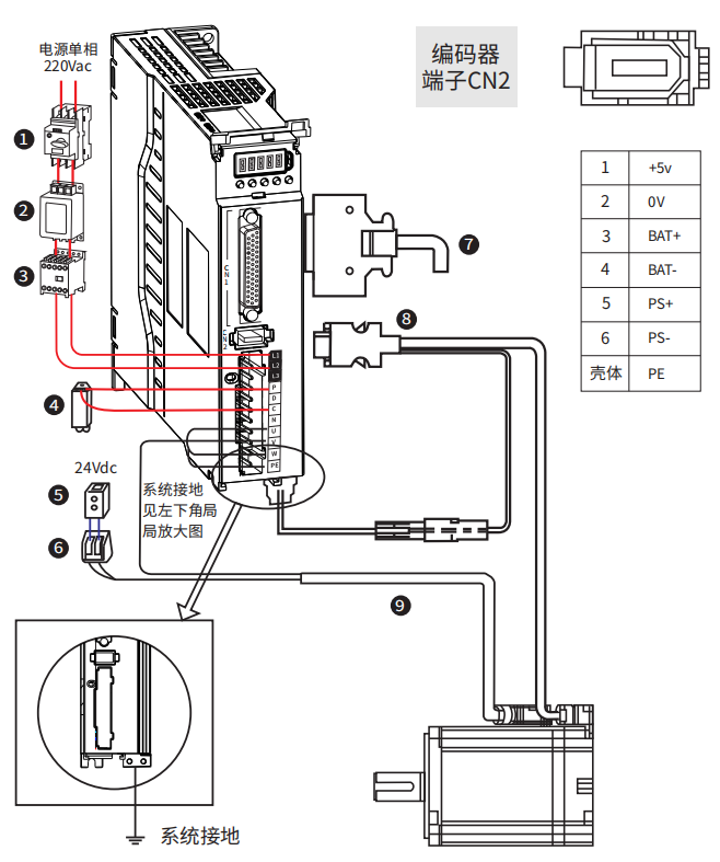
0.4KW~1.5KW servo wiring
number | name | description |
1 | Wiring circuit breaker | Cut off the circuit when the power cable overcurrent |
2 | Noise filter | Install a current filter to prevent noise from outside the power cable |
3 | Electromagnetic contactor | Turn on/off the servo power supply. Please install a surge suppressor during use |
4 | Braking resistor | When capacitance is insufficient itself, the P-C terminal should connected to an external braking resistor |
5 | Brake power supply | 24Vdc voltage source, used when servo motor with brake |
6 | Electromagnetic contactor | Brake control signal, turn on/off the brake power supply, please install surge suppressors when using. It is recommended to use servo DO controlled electromagnetic contactors |
7 | Control cable | Non standard, provide terminals, cables could be self-made or purchased separately |
8 | Encoder cable | Motor wiring, please select the appropriate length of cable according to actual needs |
9 | Motor power cable |
Figure 3-6 R8 series servo 0.4~1.5KW wiring diagram
Terminal | Name | description |
L1 | Power supply input | If power is single-phase AC 220V , connect L1 and L2 L3 vacant, do not connect |
L2 | ||
L3 | ||
P | Braking resistor terminal | When using internal braking resistors, short-circuit P and D; When using an external braking resistor, disconnect P and D and connect the external braking resistor between P and C |
D | ||
C | ||
N | ||
U | Motor connection cable | connected to the corresponding terminals of the motor U, V, W, and PE; |
V | ||
W | ||
PE |
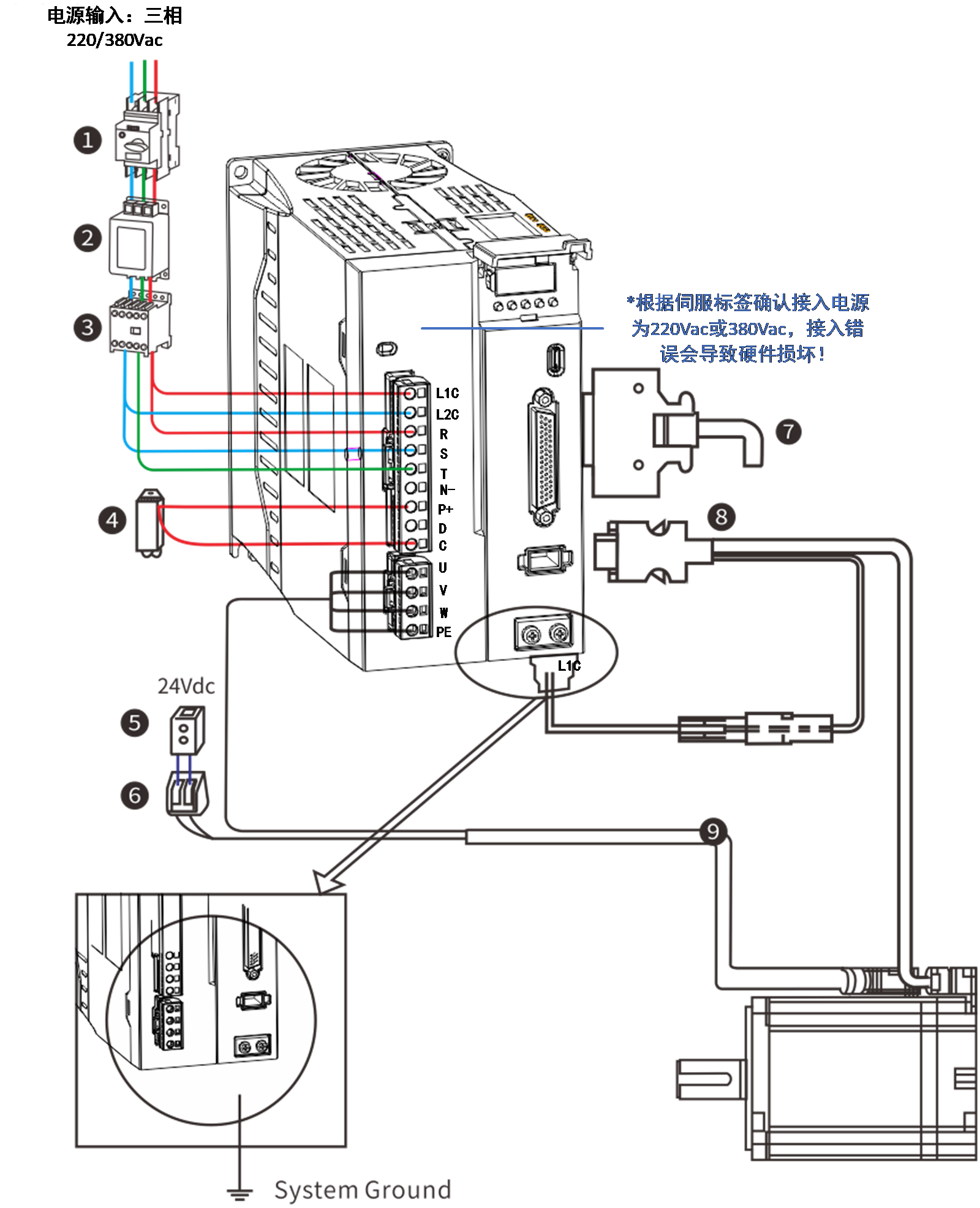
 2.6~3KW servo driver wiring
number | name | description |
1 | Wiring circuit breaker | Cut off the circuit when the power cable overcurrent |
2 | Noise filter | Install a current filter to prevent noise from outside the power cable |
3 | Electromagnetic contactor | Turn on/off the servo power supply. Please install a surge suppressor during use |
4 | Braking resistor | When capacitance is insufficient itself, the P-C terminal should connected to an external braking resistor |
5 | Brake power supply | 24Vdc voltage source, used when servo motor with brake |
6 | Electromagnetic contactor | Brake control signal, turn on/off the brake power supply, please install surge suppressors when using. It is recommended to use servo DO controlled electromagnetic contactors |
7 | Control cable | Non standard, provide terminals, cables could be self-made or purchased separately |
8 | Encoder cable | Motor wiring, please select the appropriate length of cable according to actual needs |
9 | Motor power cable |
Figure 3-7 R8series servo 2.6~3KW wiring diagram
Terminal | Name | Description |
L1C | Control power input | If 380VAC connect 2 live lines If 220VAC connect one live ,one neutral |
L2C | ||
L1 | Power supply input |
Power, connect 3 live lines (R, S ,T) |
L2 | ||
L3 | ||
P | Braking resistor terminal | When using internal braking resistors, short-circuit P and D; When using an external braking resistor, disconnect P and D and connect the external braking resistor between P and C |
D | ||
C | ||
N | ||
U | Motor connection cable | connected to the corresponding terminals of the motor U, V, W, and PE; |
V | ||
W | ||
PE |
【Notes】
- To protect the power line, please choose an air circuit breaker that matches the power capacity as the current protection device.
- Electromagnetic contactors are used in conjunction with coil surge absorbers , connect or disconnect the main power supply of the driver through a controller.
- It is strictly prohibited to use electromagnetic contactors for motor operation or shutdown, otherwise it may cause damage to the drive.
- In order to prevent interference from the motor to the driver, the power and ground wires of the motor must be connected to the terminals of the driver's shell.
【Wiring Instructions】
- Recommend using our company's servo drive cable
- Use voltage resistant cables with a voltage rating of AC600V or higher and a temperature rating of 75 ℃ or higher
- Please ensure that the bending radius of the cable is at least 10 times the outer diameter
- When used in high ambient temperatures, please choose heat-resistant cables as ordinary cables are prone to aging and brittle。
- The cable based on polyvinyl chloride resin is prone to hardening and cracking at low temperatures, and should be distinguished when used in environments below 0 ℃.
The relationship between wire specifications and allowable current is illustrated in the following example, please refer to it when selecting cables.
Example: Select the cable under the conditions of three-phase AC 220V, current 35A, and ambient temperature of 30 ℃ :
Step 1: Choose a cable with a diameter of 3.5-5.5mm2
Step 2: Calculate the applicable allowable current
Applicable allowable current
=basic allowable current x current reduction factor x current
correction factor
= 37×0.7×1.414
≈ 36.6 (A) > 36 (A) Qualified
choose a 3-core copper stranded cable with a cross-sectional area of 3.5 mm2
Step 3: If the selected cable is unqualified, increase the proposed wire diameter and repeat the above steps until it is qualified.
Basic allowable current of copper twisted cable
Nominal cross-sectional area of wire (mm2) | Basic allowable current (A) |
2~3.5 | 27 |
3.5~5.5 | 37 |
5.5~8 | 49 |
8~14 | 61 |
14~22 | 88 |
22~30 | 115 |
30~38 | 139 |
Current reduction coefficient
The reduction factor varies for different cables. When the wire used is in a synthetic resin wire shuttle, synthetic resin tube, metal wire shuttle, metal tube, or wire hose, the current reduction factor is shown in the following table.
number of lines within the same pipe | Current reduction factor |
1~3 | 0.7 |
4 | 0.63 |
5~6 | 0.56 |
7~15 | 0.49 |
16~40 | 0.43 |
41~60 | 0.39 |
> 60 | 0.34 |
The basic allowable current and current reduction factor recorded in this example may change due to specification modifications, so please confirm with the cable manufacturer before selecting the cable.
Definition of Command Terminal CN1
1)Definition of Control Signal Port
The R8 instruction terminal CN1 includes pulse and direction input pins, switch input pins, switch output pins, and encoder feedback output pins. In pulse sequence instruction mode, the diagram of each pin on terminal CN1 plug is as follows:
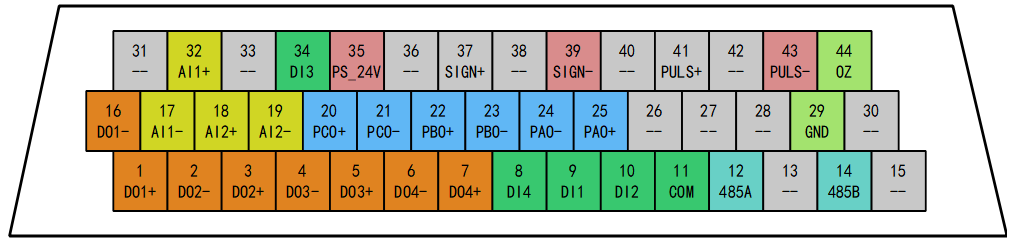
Figure 3-8 control cable CN1 definition
【Terminal Description】
- The command terminal is a DB44 pin plug. Please determine the pin sequence according to the soldering surface in the diagram.
Table 3‑3 Definition of Command Terminal CN1 Signal
function | Terminal mark | Name | Description |
Pulse input | 35 | PS_24V | Connect PLC power supply 24V |
43 | PULS- | Single ended pulse input signal/differential pulse input negative | |
41 | PULS+ | Differential pulse input positive | |
39 | SIGN- | Single ended directional input signal/differential pulse input negative | |
37 | SIGN+ | Differential pulse input positive | |
Pulse output | 9 | DIN1 | Input 1 (default function: servo enable) |
10 | DIN2 | Input 2 (default function: alarm clearing) | |
34 | DIN3 | Input 3 (default function: forward drive disabled) | |
8 | DIN4 | Input 4 (default function: negative drive disabled) | |
11 | COM | Input common terminal | |
1 | DO1+ | Output 1 (default function: servo ready) Output 2 (default function: positioning completed) | |
16 | DO1- | ||
3 | DO2+ | Output 3 (default function: brake output) Output 4 (default function: fault output) | |
2 | DO2- | ||
5 | DO3+ | Connect PLC power supply 24V Single ended pulse input signal/differential pulse input negative | |
4 | DO3- | ||
7 | DO4+ | Differential pulse input positive | |
6 | DO4- | ||
Analog | 32 | AIN1+ | Analog input channel 1, -10V~+10V (Can be used as speed and torque commands) |
17 | AIN1- | ||
18 | AIN2+ | Analog input channel 2, -10V~+10V (Can be used as speed and torque commands) | |
19 | AIN2- | ||
Frequency division output | 25 | PAO+ | Divided differential output (5V level) (The signal source can be selected as an encoder or instruction pulse) |
24 | PAO- | ||
22 | PBO+ | ||
23 | PBO- | ||
20 | PCO+ | ||
21 | PCO- | ||
44 | OZ | Single ended Z-pulse output | |
29 | GND | Driver digital ground | |
RS485 | 12 | 485/A | Supports Modbus communication |
14 | 485/B |
2)Single ended input command pulse port
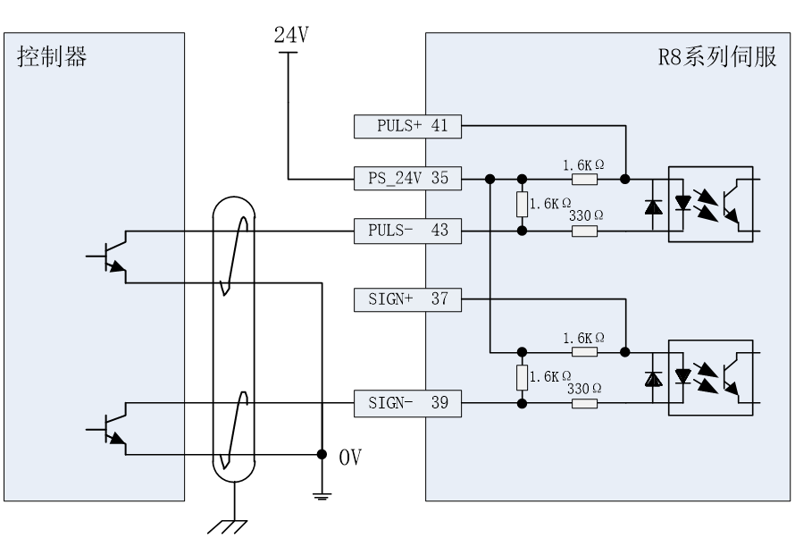
Figure 3-9 Single ended pulse input wiring (NPN connection)
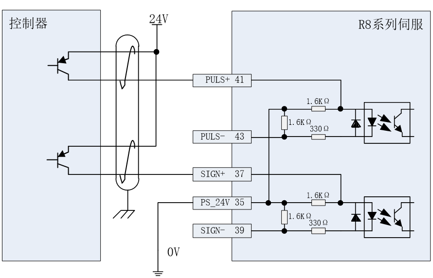
Figure 3-9 Single ended pulse input wiring (NPN connection)
3)Differential input command pulse terminal
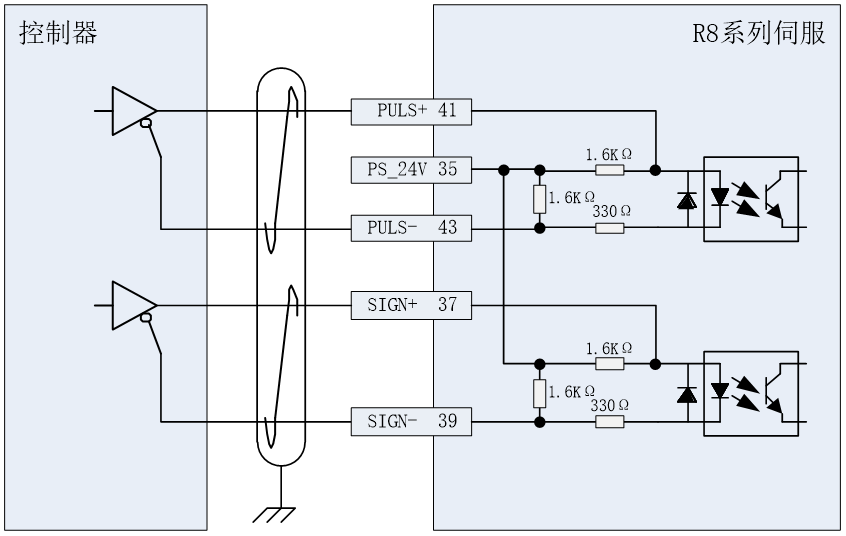
Figure 3-10 Differential pulse input wire method(Differential or 5V)
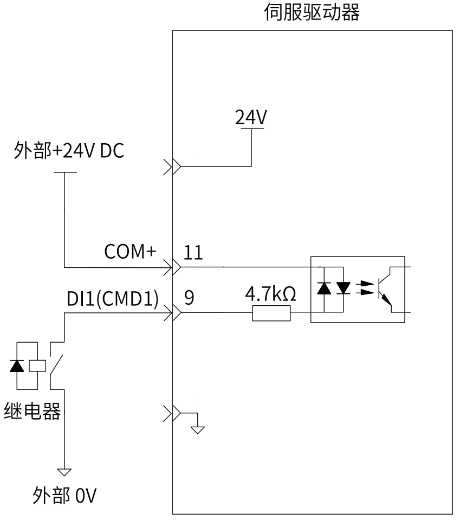
4)Digital input pin
Taking DI1 as an example, the internal circuit of the digital input terminal:
When the upper controller outputs a relay:
When the upper controller outputs an open collector circuit:
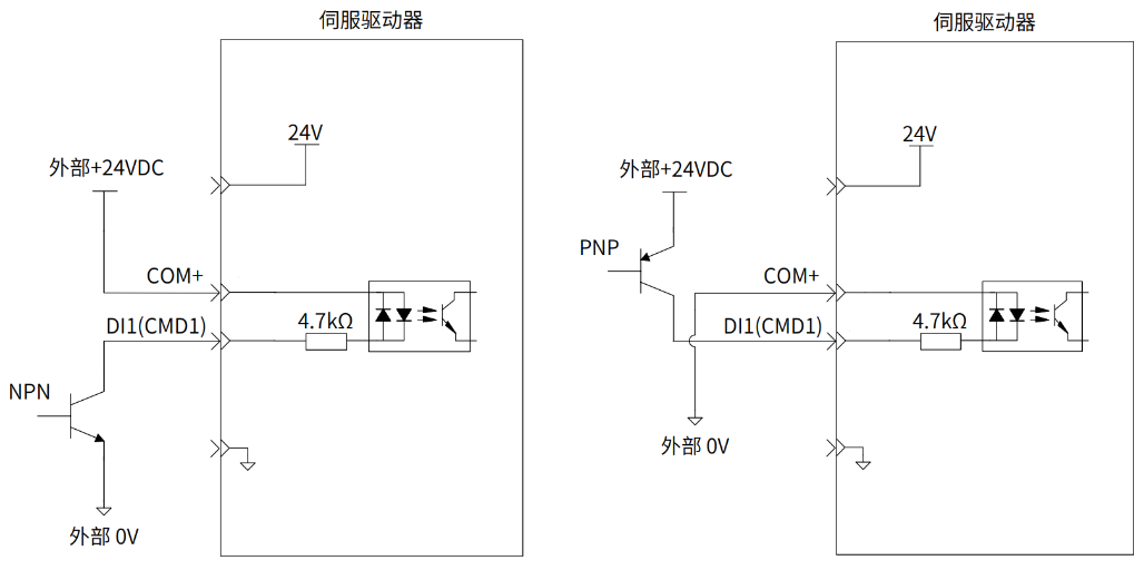
Figure 3-12 Digital input (input IO)
【 Precautions 】
- The arrows in the figure represent "input" or "output", rather than the actual direction of the current.
- Not supporting mixed use of PNP and NPN inputs.
- Do not directly connect the 24V power supply to the DI terminal, otherwise it may cause damage to the internal circuit and abnormal use of the DI terminal.
- The input circuit of the servo drive uses a bidirectional optocoupler. Please select the common collector circuit or common emitter circuit connection according to the mechanical specifications.
5)Analog input signal
Analog single ended input |
|
|
Analog differential input |
|
|
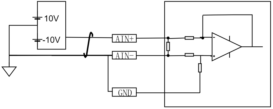
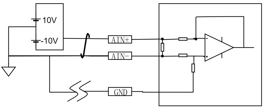
Figure 3-13 Analog Port Input
【 Precautions 】
- Speed and analog control share two analog inputs, which can be selected through parameters
- The input range of analog signal is -10~10V, and the input impedance is about 10K Ω
- If there are too many wires, short circuit GND to AIN -
6)Drive relay or optocoupler
The digital output by transistors and can drive relays or optocouplers. The reference circuit is as follows:
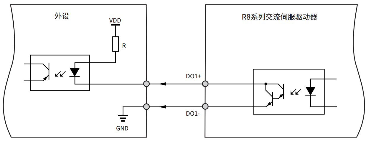
Figure 3-14 digital output (output IO, drive optocoupler)
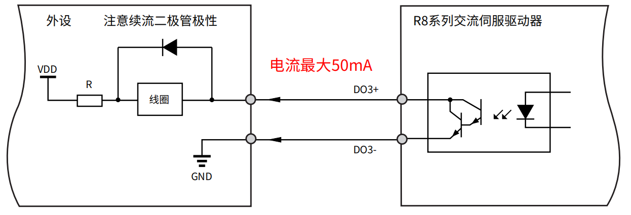 Figure 3-15 digital output (output IO, drive relay)
- 【Precautions】
- VDD:12~24V,reversing the polarity of the driving power supply can cause the driver to malfunction
- Select the appropriate resistor R based on the driving current ≤ 50mA
- The arrows in the figure represent "input" or "output", rather than the actual direction of the current
- Do not directly connect the 24V power supply to the DO terminal, otherwise it may cause damage to the internal circuit and abnormal use of the DO terminal
7)Encoder signal output pin
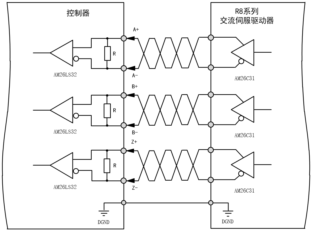
Figure 3-16 Encoder Divided Output
- 【Precautions】
- The arrows in the figure represent "input" or "output", rather than the actual direction of the current
R8 series servo drives supports encoder zero position signal Z collector open circuit output, used to drive larger loads. The reference circuit is as follows:
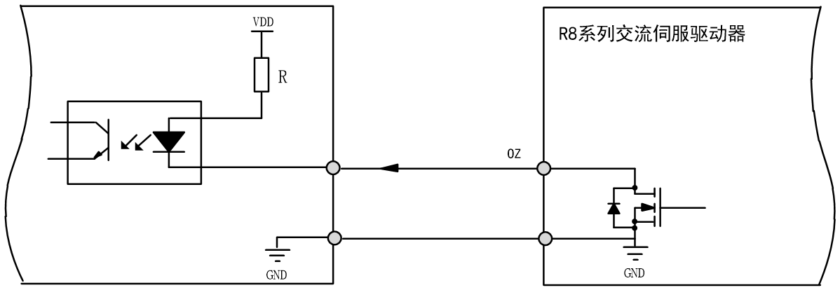
Figure 3-17 Encoder Z Signal Collector Output
- 【Precautions】
- The pulse width of the Z signal is narrow, and a high-speed optocoupler must be used to receive the signal.
- The arrows in the figure represent "input" or "output", rather than the actual direction of current flow
Confirmation of Input Signal Status
The steps to confirm the input signal status through the driver panel are as follows:
1.Press the MODE button to switch to the monitoring parameter digital display and find the o-029 parameter, then click the SET button
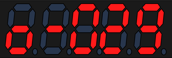
When the optocoupler is not conducting, the input is at a high level, and the upper 4 points (LED) light up. When the optocoupler is conducting, the input is at a low level, and the lower 4 points (LED) light up. For example, all four input IO digital are in a non-conductive state,from right to left is DIN1~DIN4.
3.1.9 Confirmation of output Signal Status
The steps to confirm the input signal status through the driver panel are as follows:
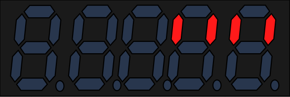
Press the MODE button to switch to the monitoring parameter digital display and find the o-030 parameter, then click the SET button

When the optocoupler is not conducting, the input is at a high level, and the upper 4 points (LED) light up. When the optocoupler is conducting, the input is at a low level, and the lower 4 points (LED) light up. For example, all four output IO digital are in a non-conductive state,from right to left is DO1~DO4.