Selection Instructions for Braking Resistors
Braking Resistance Operating Conditions
When the torque and speed of the motor are in opposite directions, energy is transmitted back to the driver from the motor end, causing the main cable voltage to increase. When it reaches the braking point, the energy can only be consumed through the braking resistor. At this point, the braking energy must be consumed according to the braking requirements, otherwise it will damage the servo drive. The braking resistor can be built-in or external. Special note: Internal and external braking resistors cannot be used at the same time。
In the following situations, the servo motor operates in regenerative mode. When using the servo driver, attention to selecting regenerative braking resistors based on the actual situation。
• With a large inertia load and high acceleration;
• Continuously descending and running on the vertical axis;;
• The servo motor is dragged by the load and runs continuously;
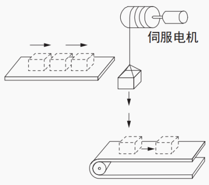
Figure 3-18 servo with brake situation
The specifications of the R8 series servo built-in regenerative resistor are shown in Table 3.5 below
Rated output | 400W | 750W | 1000W | 1.5KW | 2.6KW | 3.0KW |
Resistance value | 无 | 50Ω | 50Ω | 40Ω | 50Ω | 50Ω |
Allowable power Pa | 无 | 50W | 60W | 60W | 80W | 80W |
Table 3.4 R8 servo built-in regenerative resistor resistance and power
- Note:
*1.The R8 series servo drive with a power of 400W or more is equipped with a built-in regenerative resistor. When the power of the built-in resistor is insufficient, please calculate and add an external regenerative resistor according to the following method。
*2、When the braking function is not required, the braking function can be turned off by setting parameters. Refer to the parameter settings section P00 for parameter settings P00-05/P00-06/P00-07.
Calculation of Braking Resistance
- Ignore load torque in Reciprocating motion state
The capacity calculation of the regenerative resistor during acceleration and deceleration of the operating cycle shown in the following figure serves as an example to illustrate the calculation steps. Assuming the motor performs a reciprocating motion, the kinetic energy will be converted into electrical energy and fed back to the main cable capacitor during braking. When the main cable voltage exceeds the braking voltage, the braking resistor will consume the excess feedback energy. The motor speed curve is as follows: there are two decelerations from rated speed to 0 within one motion cycle, ignoring the load torque, friction torque, and energy consumption of servo motor coil resistance during the deceleration process.
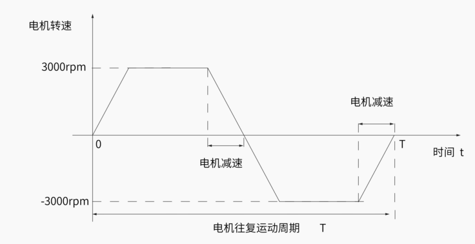
Figure 3.19 diagram of acceleration and deceleration motion cycle of motor
step | Calculation project | symbol | Calculation formula and explanation |
1 | Rotating energy of servo system | Ei | Calculate based on the load inertia ratio Jr, actual rotational speed W, and the number of decelerations N during the motion cycle, combined with Table 3.7 Em |
2 | Find the absorbed energy of the servo unit | EC | Select according to Table 3.7 based on the servo model |
3 | Calculate the energy consumed by the regenerative resistor | EK | EK = Ei - EC |
4 | Calculate the average power of the regenerative resistor | WK | WK = EK /(0.2xT) |
Table 3.5 Calculation Table of Servo Regenerative Resistance Power
Attachment: ES-EK unit is joules; WK unit is watts; T is the cycle of repeated operation of the servo motor, unit is seconds; In the calculation formula of WK in the table above, 0.2 is the value when the load rate of the regenerative resistor is 20%. The load rate of the regenerative resistor is related to the heat dissipation conditions, and an appropriate coefficient can be selected for calculation according to the following text.
The capacity of the regenerative resistor should be set to a value that matches the allowable capacity of the connected external regenerative resistor. The set value varies depending on the cooling state of the external regeneration resistor.
- When using self cooling method (natural convection cooling): set to a value below 20% of the regenerative resistance capacity (W).
- When using forced air cooling method: set to a value below 50% of the regenerative resistance capacity (W)。
example When the capacity of the self cooling external regeneration resistor is 100W, 100W × 20%=20W. The servo related parameters can be changed by setting P00-05 to select the external braking ,and resistor heat dissipation method.
The energy data generated by the motor from a no-load speed of 3000rpm to a standstill is as follows:
Motor capacity (W) | Servo motor mode | Inertia kg.cm^2 | Braking energy generated from a no-load speed of 3000rpm to a standstill Em (J) | The maximum braking energy that can be absorbed by a capacitor Ec(J) |
100 | 40HK-A00330-CS2B2 | 0.06 | 0.3 | 14.7 |
40HK-A00330-CS2B3 | 0.08 | 0.4 | ||
200 | 60HK-A00630-CS2B2 | 0.3 | 1.48 | |
60HK-A00630-CS2B3 | 0.32 | 1.58 | ||
60HK-A00630-CS2B3-A | 0.28 | 1.38 | ||
400 | 60HK-A01330-CS2B2 | 0.65 | 3.21 | |
60HK-A01330-CS2B3 | 0.67 | 3.31 | ||
60HK-A01330-CS2B2-A | 0.52 | 2.57 | ||
750 | 80HK-A02430-CS2A2 | 1.71 | 8.46 | 14.7 |
80HK-A02430-CS2A3 | 1.8 | 8.9 | ||
80HK-A02430-CS2A2-A | 1.48 | 7.32 | ||
1000 | 80HK-A03230-CS2A2 | 2.15 | 10.63 | 24.9 |
80HK-A03230-CS2A3 | 2.24 | 11.08 | ||
80HK-A04025-CM2A2-A | 2.4 | 11.87 | ||
1000 | 130HK-A04025-CS2A2 | 7.2 | 35.6 | |
130HK-A04025-CS2A3 | 8.7 | 43.02 | ||
130HK-A04025-CS2A2-A | 8.5 | 42.03 | ||
1300 | 130HK-A05025-CS2A2-A | 12.6 | 62.31 | 37.4 |
1500 | 130HK-A06025-CS2A2 | 10.3 | 50.93 | |
130HK-A06025-CS2A3 | 11.8 | 58.35 | ||
130HK-A10015-CS2A2-A | 19.4 | 95.93 | ||
2000 | 130HK-A07725-CS2A2 | 10.3 | 50.93 | 44.5 (220V drive) 32.7 (380V drive) |
130HK-A10020-CS2A2 | 12.7 | 62.8 | ||
130HK-A07725-CS2A2-A | 15.3 | 75.66 | ||
2300 | 130HK-A15015-CS2A2 | 19.7 | 97.42 | |
130HK-A15015-CS2A2-A | 27.7 | 136.98 | ||
2600 | 130HK-A10025-CS2A2 | 12.7 | 62.8 | |
130HK-A10025-CS2A2-A | 19.4 | 95.93 | ||
3000 | 130HK-A19015-CS2A2-A | 35.4 | 175.05 |
Table 3-6 R8 series servo energy absorption
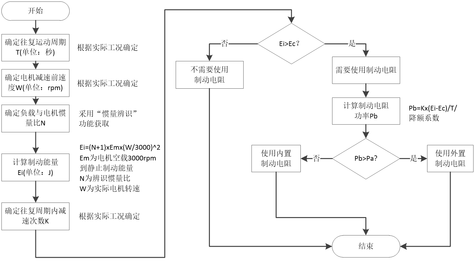
Figure 3.20 Calculation of Braking Resistors
- Example: A R8-2208P servo is paired with an 80HK-A02430-CS2A2 motor for reciprocating periodic motion. T= 2S, When operating at a maximum speed of 3000rpm and a load inertia ratio of 10.00, with 2 decelerations per cycle, the required braking resistor power is:
==78.36W |
When the braking energy is greater than the capacity of the built-in braking resistor Pa=40W (which can be found according to Table 3.5), and an external braking resistor needs to be used. The recommended power of the external braking resistor is Pb/(1-80%)=390W:
==8.56W |
When the braking energy is greater than the capacity of the built-in braking resistor Pa=40W ,no need add an external braking resistor。
If the driver operates at an ambient temperature above 50 ℃, please use it with a rated built-in resistance of 20%.
Use an external braking resistor
When Pb>Pa An external braking resistor needs to be connected. At this point, depending on the cooling method of the braking resistor, set P00.05 to 2 or 3.
When the external braking resistor needs to be reduced by 80%,that is:Pr=Pb/(1-80%),And ensure that it is greater than the minimum resistance value allowed by the driver.Connect the two ends of the external braking resistor to "P ⊕" and "C" respectively, and remove the wire between terminals "P ⊕" and "D".
Please refer to Chapter 3.2 Wiring and Terminal Definitions for the wire specifications. According to the different cooling methods of the braking resistor, set P00-05 to 1 or 2 and confirm the following parameters:
Function code | Data name | Set range | unit | value | Effective method | Set method | Set mode |
P00-06 | External regenerative resistor power | 1~65535 | W | 40 | Effective immediately | Stop Set | Ordinary users |
P00-07 | External regenerative resistor resistance value | 1~1000 | Ω | 50 | Effective immediately | Stop Set | Ordinary users |
Related parameters
Function code | Data name | Set range | unit | value | Effective time | Set method | Set mode |
|---|---|---|---|---|---|---|---|
P00-05 | Select set | 0- Use built-in regenerative resistor 1. Use an external regenerative resistor 2. Use an external regeneration resistor and cool it down with a fan 3- Do not use regenerative resistors | -- | 0 | immediate | Stop set | Ordinary users |
P00-06 | resistor power | 1~65535 | W | 40 | immediate | Stop set | Ordinary users |
P00-07 | resistor value | 1~1000 | Ω | 50 | immediate | Stop set | Ordinary users |
- Reverse charging state with load torque
In some special situations, the motor torque output is opposite to the direction of rotation, and the motor performs negative power. External energy is generated by the motor and fed back to the driver. When the load is in a continuous power generation state, it is recommended to adopt a common DC bus scheme or use external braking resistors to release the energy of the bus capacitor.
Taking 750W (rated torque 2.39N · m) as an example, when the external load torque is 60% of the rated torque and the speed reaches 1500rpm, the power feedback to the driver is (60% × 2.39) × (1500 × 2 π ÷ 60)=225W. Considering that the braking resistor needs to be reduced by 80%, the power of the external braking resistor is 225 ÷ (1-80%)=1125W, and the resistance value is 50 Ω