Auxiliary Function Parameters (Fun Group Parameters)
Auxiliary functions are used to perform functions related to setting and adjusting servo units.
Display on the panel ,Read as P12 group of auxiliary function parameters in the upper software or 485 bus.
F-000 servo restart
The servo restart function can perform a soft reset of the servo and restore the power on state of the servo drive.
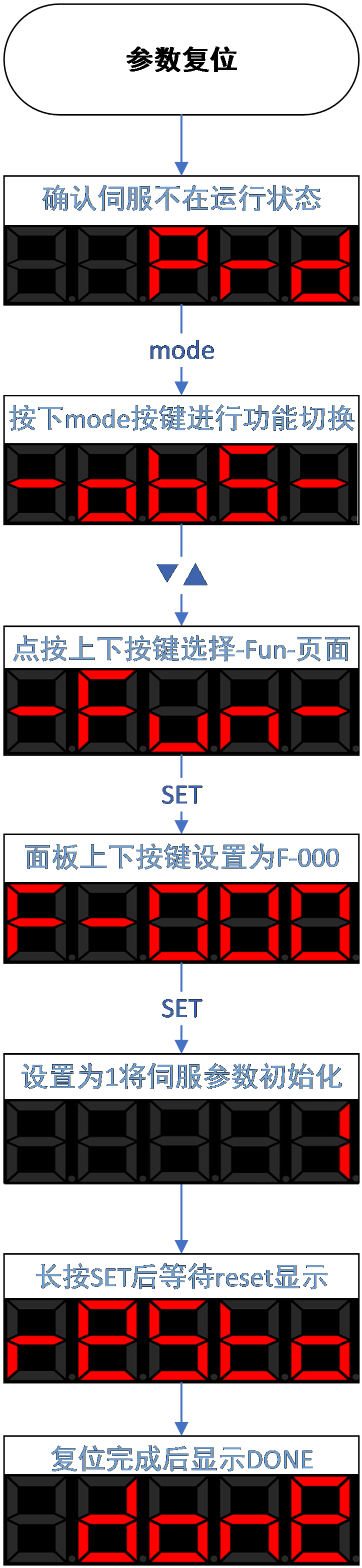
Figure 4.4 servo restart diagram
Code | Name | Set range | unit | value | Effective Mode | Set mode | Relevant Mode |
P12-00 | Servo restart | 0-none operate 1-servo restart 2-restore factory mode | -- | 0 | Effective immediately | anytime | Ordinary user |
F-001 Alarm clear
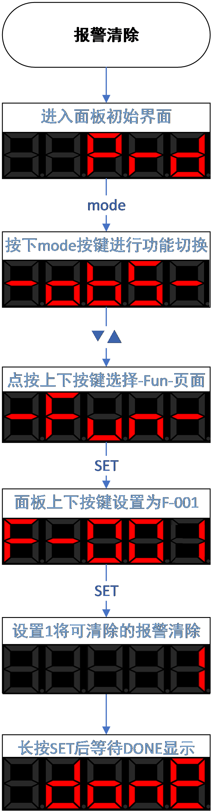
Figure 4.5 Alarm clear diagram
The alarm clearing function can clear the current alarm and restore the servo operation status. There are two ways to clear the alarm:
① Write '[1] Clear current alarm' through the function code 'F-001 Alarm Clear'.
② Use the DI terminal to input the alarm clearing signal. By default, DI2 is configured with the alarm clearing function ("P1-05 DI2 terminal function selection" is set to "[2] alarm clearing"). when DI2 input “ON” will trigger the alarm clearing action.
- Attention
- If you need to clear the alarm when the enable signal is in effect, please set the P0B-29 parameter to 1
- Please check and eliminate the cause of the alarm before the alarm clearing action. If the current alarm condition still exists, the alarm clearing action will not take effect。
- For some alarms that need to be eliminated by changing parameter settings, it is important to confirm whether the modified parameters need to be restarted to take effect, such as the "AL.113 restart prompt" is a low priority warning and will not prompt when there are other alarms present.
Not all alarms can be cleared. You can check and confirm whether the alarm can be cleared through the "6.3.1 Software Alarm Attribute Table"
F-002 JOG enable
To test operate the servo motor and driver, the JOG operation function can be used to confirm whether the servo motor can rotate normally, and whether there are any abnormal vibrations or sounds during rotation. This parameter can be set through the panel.
The operation of JOG is located in Fun-002, and the servo drive needs to be in the non enable and non alarm state at this time.
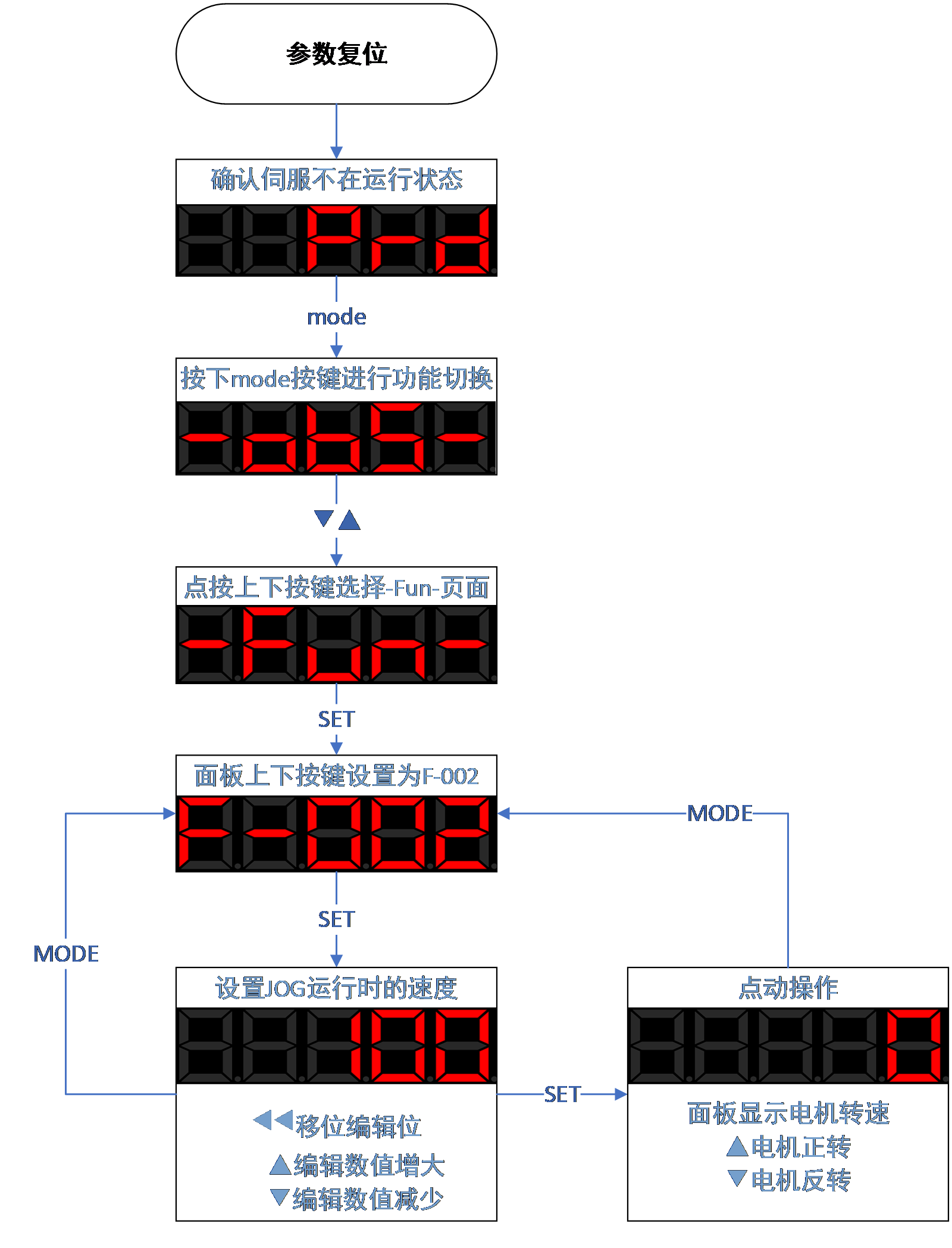
Figure 4.6 JOG test running diagram
F-003 Inertia identification
Inertia identification is the foundation of debugging. When ensuring that the motor has a movable stroke of more than 1 circle in both directions,. If the stroke does not meet the requirements or the load inertia ratio is too large (>30 times), please estimate a suitable inertia ratio and set value to C-011. The process of inertia identification is shown in the following figure:
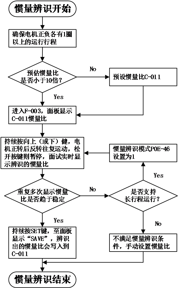
Figure 4-7 process of inertia identification
- Precautions:
- If under the default value of C-011=100%, the actual speed cannot keep up with the command due to the inertia ratio being too small, resulting in identification failure, the load inertia ratio C-011 needs to be preset. The preset value is recommended to gradually increase from 500% until it can be identified normally.。
- Offline inertia identification mode is generally recommended to use triangular wave mode. If there are situations where the identification effect is not good, try using step rectangular wave mode.
- Pay attention to the mechanical stroke when P0E-46=1 to prevent accidents caused by overtravel during offline inertia identification.
Relevant code below:
Code | Name | Set range | unit | value | Effective Mode | Set mode | Relevant Mode |
P0E-46 | Offline inertia identification mode | 0 – triangular wave mode 1 – JOG mode | 0 | Effective immediately | Stop set | ALL | |
P0E-47 | Offline inertia identification speed amplitude | 100~1000 | rpm | 500 | Effective immediately | Stop set | ALL |
P0E-48 | Offline inertia identification acceleration and deceleration time | 20~800 | ms | 125 | Effective immediately | Stop set | ALL |
P0E-49 | Offline inertia identification waiting time | 50~10000 | 800 | Effective immediately | Stop set | ALL | |
P0E-50 | Offline inertia identification of stroke cycles | - | display | ALL |
Conditions for effective inertia identification:
● The actual maximum speed of the motor is higher than 150rpm;
● The actual speed during acceleration and deceleration reaches the rated speed;
● The load torque is relatively stable and cannot undergo drastic changes;
● Maximum identifiable inertia of 30 times;
● When the mechanical rigidity is extremely low or the backlash of the transmission mechanism is large (such as chains), it may be identification failure。
F-004 Absolute encoder function
This parameter is an encoder related parameter that can be used to modify encoder related functions
When P12-04 is set to 1, it can clear alarms such as AL.41 (absolute encoder counting abnormal), AL.43 (absolute encoder multi turn counting error), AL.44 (absolute encoder multi turn counter overflow), AL.45 (absolute encoder battery failure), AL.46 (absolute encoder battery alarm), AL.47 (absolute encoder overheating), etc.
When P12-04 is set to 2, the absolute encoder can be reset and restarted
When P12-04 is set to 3, the absolute encoder single turn data can be reset to zero. Please refer to section 5.11 for modification of this function. Do not change it arbitrarily, otherwise it will cause abnormal motor electrical angle.
Code | Name | Set range | unit | value | Effective Mode | Set mode | Relevant Mode |
|---|---|---|---|---|---|---|---|
P12-04 | Absolute encoder reset operation | 0-non operate 1-Absolute encoder reset alarm 2-Absolute encoder reset 3-single turn data reset to 0 | -- | 0 | Effective immediately | Stop set | Ordinary user |