1. Automatic control IST
1. Automatic control IST
1.1. Instruction Description
The IST instruction customizes a comprehensive system for multi-mode automatic control for stepper programs, where users input a given switch position to switch modes and control the program.
Given a starting bit as an input switch (taking M20 as an example), M20~M27 will be used by IST. These bit registers act as switches to manipulate IST instructions to control the stepper program. These bits are only valid when the rising edge is triggered.
M20: Switch to manual mode. M21: Switch to return to origin mode. M22: Switch to single step mode. M23: Switch to single cycle mode. M24: Switch to automatic mode. M25: Origin regression is initiated. M26: Start. M27: Stop.
When the M20 rising edge is triggered, IST will immediately enter manual mode. Similarly, the rising edges of M21, M22, M23, and M24 enter the return to origin mode, single step mode, single cycle mode, and automatic mode, respectively.
1.2. Register usage
IST will involve the following registers, please do not program them as regular registers:
| Memory Name | Function | Read/Write Permissions |
|---|---|---|
| D_8048 | IST current mode (0: not enabled, 1: manual, 2: return to origin, 3: single step, 4: single cycle, 5: automatic) | Read |
| M8021 | IST transfer begins | Read&Write |
| M8022 | IST Start Pulse | Read |
| M8023 | IST Origin Regression Completed | Read |
| M8024 | IST Origin Condition | Read&Write |
| M8025 | IST All outputs are prohibited from resetting | Read&Write |
| S_0 | Manual initialization status | Read&Write |
| S_1 | Initialization state of origin regression | Read&Write |
| S_2 | Automatic initialization status | Read&Write |
1.3. Attentions
Please use this command at the beginning of the main program, with the input condition being M8151.
Only one IST instruction can be written in the program.
1.4. Equivalent ladder diagram of IST instruction
The detailed content of the coil register M and status register that are automatically controlled using the IST instruction is shown in the equivalent ladder diagram below. (As a reference knowledge, please read it once)
In addition, this equivalent ladder diagram cannot be written as a program
1.4.1. A. IST current mode (D8048) related
D8048 is related to the current mode of IST (manual, return to origin, single step, single cycle, automatic). The initial value is 0, which is controlled based on the rising edge of the IST input signal under certain conditions.
The three modes of single cycle, single step, and automatic use the same program, so they are classified as one automatic mode class. This type of mode can only be switched under the condition of origin regression.
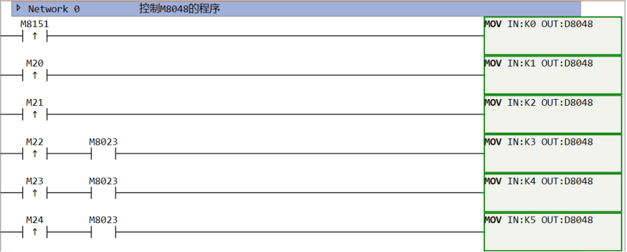
图1 IST mode transfer
1.4.2. b. Start transferring (M8021) related
In automatic mode, M8021 only operates when the start button (M26) is pressed, especially in continuous mode, where it performs a self hold action and is released when the stop button (M27) is pressed.
Entering manual mode or return to origin mode will reset M8021.
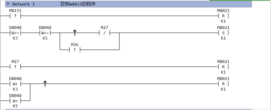
图2 Start transfering
1.4.3. c. Starting pulse (M8022) related
The rising edge of the starting pulse in a single cycle is used to indicate the start of automatic mode or origin regression mode. So the start signal (M65) and the origin regression start signal (M25) are only valid in the corresponding mode.
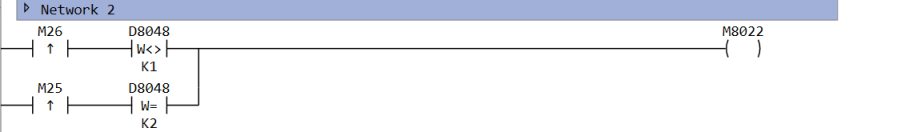
图3 Start pulse
1.4.4. d. Related to sequential control states (S0, S1, S2)
S0, S1, and S2 are the starting states of manual mode, origin regression mode, and automatic mode, respectively. When entering one of the modes, all other states must be reset and the corresponding starting state must be set.
At this point, all Y outputs will be reset by default, and M8025 can be set to ON to cancel this operation.
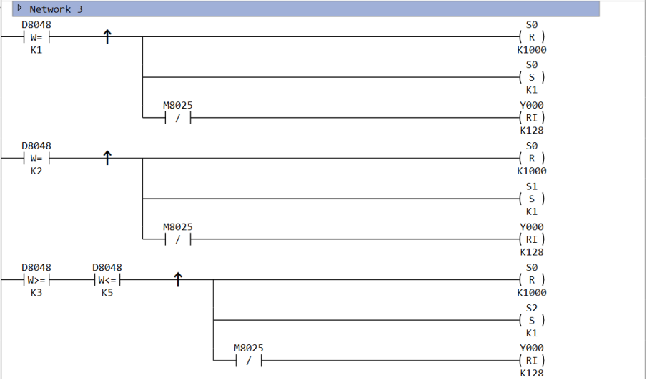
图4 Sequential Control Status
1.4.5. e. Origin regression completion flag (M8023) related
According to the input of each mode, while switching the initialization state, it is also possible to control M8023.
However, M8043 and M8044 (origin regression condition) require user program control.
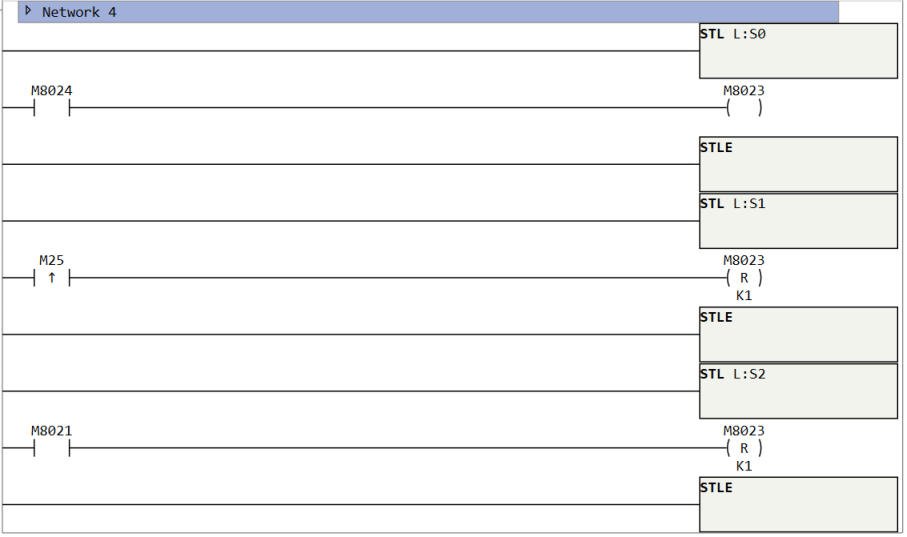
图5 Origin Regression Completion Flag
1.5. Example of use (robotic arm control)
Action requirement: Separate two balls of different sizes and store them in different boxes. Configure a touch screen or console for control.
Operation of robotic arm: descend, clamp, ascend, move to the right, descend, release, ascend, move to the left, and complete the transportation of the ball in sequence.
IO settings: The PLC outputs Y0 to raise the arm, Y1 to lower, Y2 to move right, Y3 to move left, and Y4 to grip the handle. X0 is used to sense the weight of the ball (reset to ON, otherwise OFF). When the arm reaches the same vertical line as the position to pick up the ball, X1 is set to ON, X2 is set to ON when it reaches the vertical line of the large ball box, X3 is set to ON when it reaches the vertical line of the small ball box, X4 is set to ON when it reaches the top horizontal line, and X5 is set to ON when it reaches the bottom horizontal line.
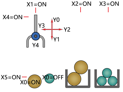
图6 Action Flow Diagram
| Operation mode | Action content |
|---|
Manual operation: Use each button to operate the start and stop modes of each load.
| Origin Regression: Press the origin regression button to automatically return the machine to the origin mode. | ||
| Automatic | Single step operation: | Each time you press the start button, you advance one process. |
| Single cycle operation: After pressing the start button at the origin position, execute an automatic cycle and stop at the origin position. If the stop button is pressed halfway, the process will stop. Pressing the start button again will start running from the previous position and then automatically stop at the origin. | ||
| Automatic mode: After pressing the start button at the origin position, continuous repetitive operation begins. After pressing the stop button, it will run to the origin position and stop. |
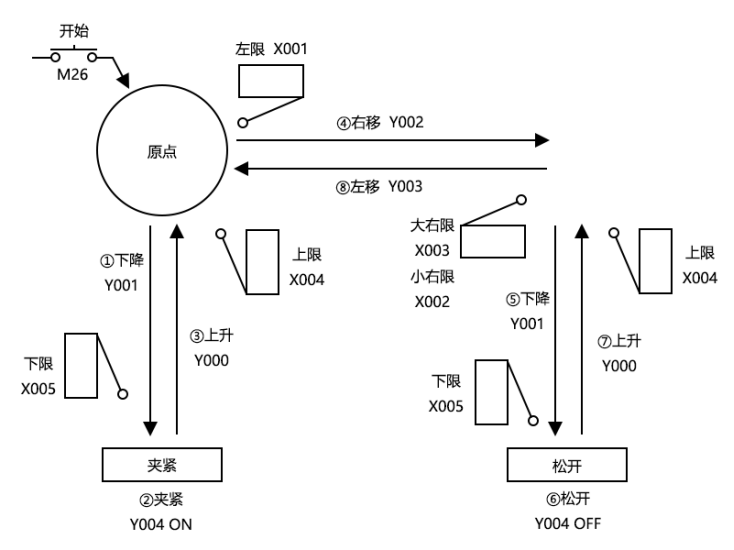
图7 Transmission Machinery
Using the top left as the origin, move the workpiece from left to right in the order of descent, clamping, ascent, rightward movement, descent, release, ascent, and leftward movement. When descending/ascending, use dual solenoid valves (two inputs for driving/non driving) for left/right movement, and use a single solenoid valve (only activated when powered on) for clamping.
1.6. Special auxiliary relay (M) for IST instruction
The auxiliary relay (M) used in IST instructions is divided into two categories: automatic control based on the specific situation of the instruction itself, and program control based on the preparation and control purpose of operation.
1.6.1. a) M8020:forbbiden transfer
Once this auxiliary relay is activated, all state transitions are prohibited.
M8020 and IST are independent of single step and single cycle interrupts In fact, IST uses a different mechanism than M8020. Using the ISTNEXT instruction can have the same effect as triggering the start signal and also reset M8020.
1.6.2. b) M8021: Start transfer
As an auxiliary relay that serves as a transition condition from the initialization state S2 to the next state.
| Occasion | Action |
|---|---|
| Manual mode | No action. |
Origin Regression Mode
Step mode only operates when the start button is pressed
| Single cycle mode | In the initial state, it operates when the start button is pressed, cycles once, and returns to the initial state. The action will be maintained until a process cycle is completed, and will pause when the stop button is pressed |
| Automatic mode | The action is maintained when the start button is pressed, and released when the stop button is pressed. |
1.6.3. c) M8022: Start pulse
Only the momentary action when the start button is pressed.
1.6.4. d)M8027: STL monitoring is effective
After setting M8027 to ON, STL monitoring becomes effective, and the status numbers (S0~S999) during the action are saved in special registers D8040~D8047 in ascending order.
For performance reasons, IST will not set M8027 to ON by default. If necessary, it will be manually set in the user program
Therefore, up to 8 action status numbers can be monitored.
In addition, if any of these states act, the special auxiliary relay M8026 also acts.
1.6.5. e) M8023: Origin regression completed
In the origin regression mode, when the machine returns to the origin, please use the user program to activate this special copy relay (M).
1.6.6. f) M8024:Origin condition
Please drive this special auxiliary relay after detecting the origin condition of the machine, which is a valid signal in all modes.
1.6.7. g) M8025:Prohibit all output resets
After switching between manual mode, origin regression mode, and automatic mode, all outputs and action states are reset when the machine is not at the origin position. But if M8045 is driven first, only the action state will be reset.
1.7. Program Example
1.7.1. a) Main program
The main program needs to complete three steps:
Check the origin condition and control the M8024 register.
Call the IST instruction, with M20~M27 as the 8 outputs.
Implement three programs corresponding to three pattern classes for clear management. Here, three sub programs can be implemented to call them.
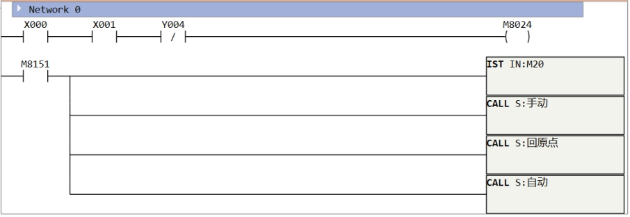
图8 main program
1.7.2. b) Manual mode
n manual mode, perform different actions based on different inputs.
The status bit of manual mode is S0, which is turned on (S0=ON) when entering this mode. This state will not transfer to any other status bit, and will only be controlled by the user on the screen through Modbus to transmit the control bit to the PLC for corresponding operations. Press the M30 button once to close the gripper, press the M31 button once to release the gripper, press the M32 button to raise, press the M33 button to lower, press the M34 button to move left, and press the M35 button to move right.
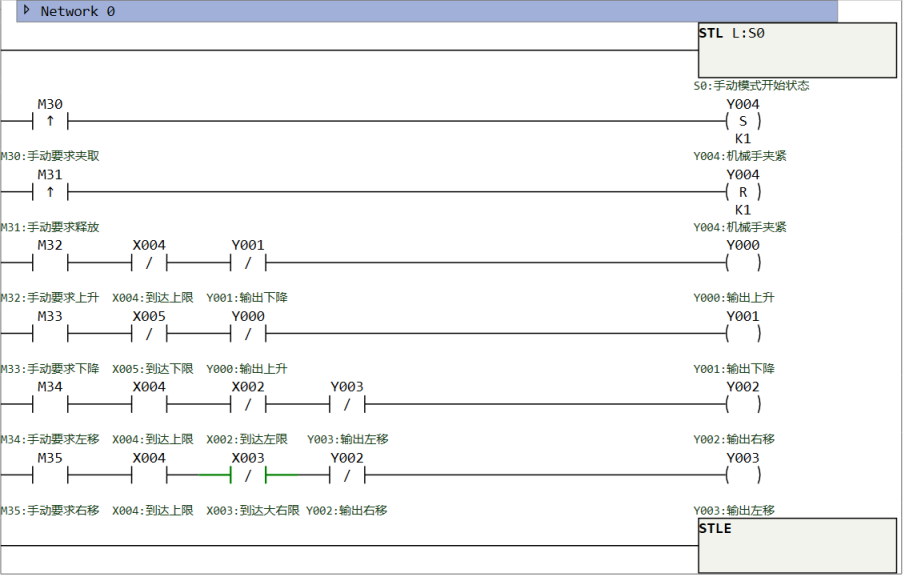
图9 Manual mode
1.7.3. c) Return to Origin Mode
When IST is in this mode, it is necessary to manipulate the robotic arm to its original position. The default position of the robotic arm is the top left corner, so reaching the leftmost and topmost positions completes the task. Write SFC program here, with S1 as the starting state bit for the return to origin mode.
Reset the last state after returning to the origin, remember to set M8023 (return to origin completed).
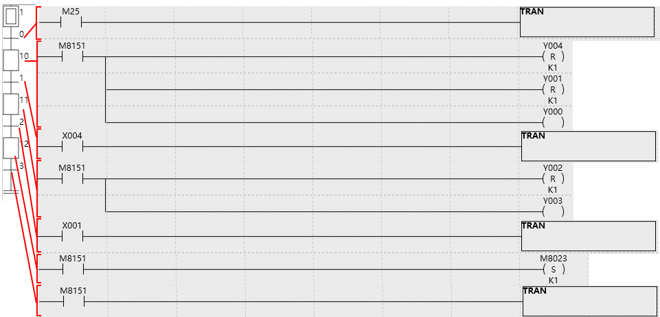
图10 Return to Origin Mode
1.7.4. d) Single step/single cycle/automatic mode
These three modes share the same SFC program, starting from state S2, and the specific control is handled by IST. The differences are as follows:
Single step mode: When entering a certain state bit, even if the conditions are met, it will not transition to the next state bit. Only when the user presses the start button (M25 rising edge) will it transition to the next state.
Single cycle mode: In this mode, it will automatically run one cycle starting from S2 and return to S2, and then wait for the start signal (M25 rising edge) before continuing to run the next cycle.
Automatic mode: In this mode, the entire process will run automatically and the work will be completed fully automatically.
Switching back and forth between these three modes does not require restarting the automatic system, and the active state will remain in the current state instead of returning to S2. However, switching between the three programs (manual program, return to origin program, automatic program) requires returning to the initial states S0, S1, S2.
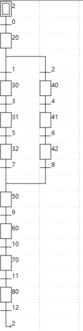
图11 Single step/single cycle/automatic mode

图12 transfer 0 program

图13 status 20 program

图14 transfer 1 program

图15 transfer 2 program
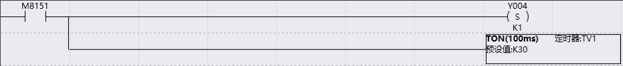
图16 status 30 program
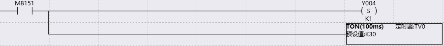
图17 status 40 program

图18 transfer 3 program

图19 transfer 4 program

图20 status 31 program

图21 status 41 program

图22 transfer 5 program

图23 transfer 6 program

图24 status32 program

图25 status 42 program

图26 transfer 7 program

图27 transfer 8 program

图28 status 50 program

图29 transfer 9 program
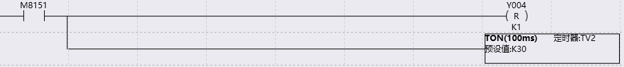
图30 status 60 program

图31 transfer 10 program

图32 status 70 program

图33 transfer 11 program

图34 status 80 program

图35 transfer 12 program