timer
A timer is a control that uses a time condition to trigger a specific
function.
In the SKTOOL configuration software, the timer is used as a control
triggered by macro commands.
Click on the toolbar
![]() or double-click on an existing property timer will enter the timer settings
page:
or double-click on an existing property timer will enter the timer settings
page:
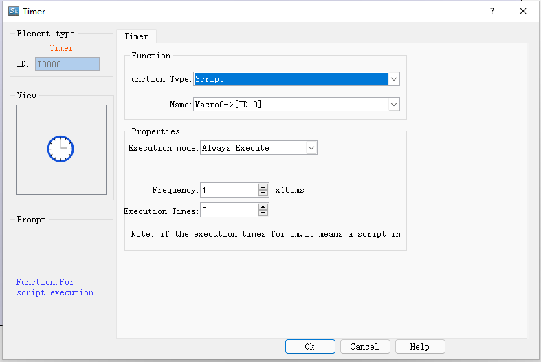
Control mode: Select the execution mode of macro instruction as always execute or address trigger.
1. "Always execute" is always executed according to the set frequency, and if always trigger is selected, the selected macro command will always be executed according to the set frequency when the project is running;
2. "Address trigger" means that when the value of the specified bit is 1, it will execute at the set frequency, and when the value of the specified bit is 0, the macro command will not be executed.
Address: When the execution mode of "address trigger" is selected, the address input field will appear, and the bit that controls the execution of this macro instruction will be input here. When the value of this bit is 1, the macro instruction is executed.
Execution frequency: The frequency at which the selected macro is executed. The range is 0.1~ 60S.
Execution times: The number of times the selected macro instruction is executed. When the number of times is 0, the macro instruction will be executed all the time.
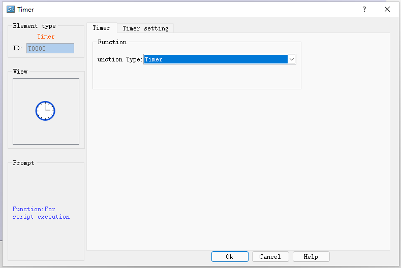
Function type: Select the type of function to be executed. The function controlled by timer in HMITOOL configuration software is macro instruction.
Name: The name of the macro to be executed. The timer cannot be set when there is no macro command.
Use the timer variable to enable the timer function. The timer variable combination contains the following six variables:
|
timer variable |
variable type |
narrative |
|
Input bit (IN) |
bit variable |
timer master switch |
|
Timing Bit (TI) |
bit variable |
Set ON when timing starts |
|
Output bit (Q) |
bit variable |
Set to ON when the setting is complete |
|
Preset Time (PT) |
word variable word |
Set timer time value |
|
Elapsed time (ET) |
word variable word |
Displays the current elapsed time of the timer |
|
reset bit (R) |
bit variable |
Reset the current timer elapsed time (ET) to zero |
set up
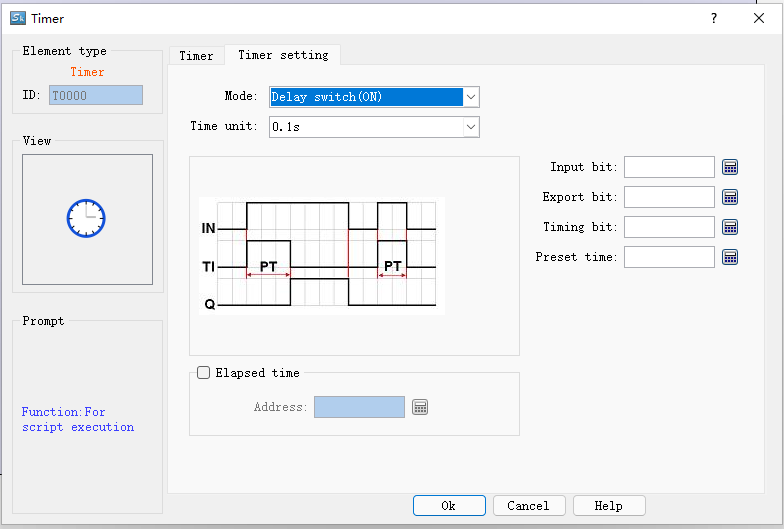
Select the function button timer on the toolbox, select the timer in the function selection, this will pop up the timer setting, the default mode is the delay switch (ON), the default time unit is 0.1 seconds, the interface is as follows:
You can see the property setting address options at the bottom right, input bit, export bit, timing bit, preset time, enable elapsed time, and press the OK button after setting each property correctly, you can add a new one to the current configuration screen. The "Timer" component, as shown in the following figure:
The following is an introduction to the functions of each mode:
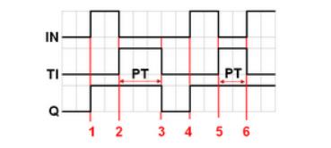
1. Delay switch (ON)
Input bit (IN): Input bit (IN): the main switch of the timer;
Timing bit (TI): Set ON when timing starts.
Output bit (Q): Set to ON after the timing is over.
Preset Time (PT): Set the timer time value.
Elapsed time (ET): Displays the current elapsed time of the timer.
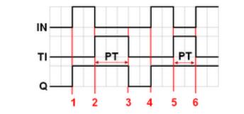
As shown in FIG:
1) When the input bit IN is set to ON, the timing bit TI is turned on, the elapsed time ET starts to count, and the output bit Q remains OFF.
2) When the counted time ET is equal to the preset time PT, the counted bit TI is turned off, and the output bit Q is turned on at the same time.
3) When the input bit IN is set to OFF, the output bit Q is turned off, and the elapsed time ET returns to zero.
4) When the input bit IN is set to ON, the timing bit TI is turned on, the elapsed time ET starts to count, and the output bit Q remains OFF.
5) When the input bit IN is set to OFF before the counted time ET reaches the value of the preset time PT, the counted time TI will be turned off and the counted time ET will return to zero.
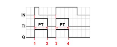
2. Delay switch (OFF)
Input bit (IN): The main switch of the timer.
Timing bit (TI): Set ON when timing starts.
Output bit (Q): Set to ON after the timing is over.
Preset Time (PT): Set the timer time value.
Elapsed time (ET): Displays the current elapsed time of the timer.
As shown in FIG:
1) When the input bit IN is set to ON, the timing bit TI remains OFF, the output bit Q is turned on, and the elapsed time ET returns to zero.
2) When the input bit IN is set to OFF, the timing bit TI is turned on, the output bit Q remains ON, and the counted time ET starts to count.
3) When the elapsed time ET is equal to the preset time PT, the output bit Q and the timing bit TI are turned off.
4) When the input bit IN is set to ON, the timing bit TI remains OFF, the output bit Q is turned on, and the elapsed time returns to zero.
5) When the input bit IN is set to OFF, the timing bit TI is turned on, the output bit Q remains ON, and the counted time ET starts to count.
6) When the input bit IN is set to ON before the counted time ET reaches the value of the preset time PT, the counted bit TI is turned off, while the output bit Q remains ON, and the counted time ET returns to zero.
3. Pulse start switch
Input bit (IN): Main switch of the timer.
Timing bit (TI): Set ON when timing starts.
Output bit (Q): Set to ON after the timing is over.
Preset Time (PT): Set the timer time value.
Elapsed time (ET): Displays the current elapsed time of the timer.
As shown in FIG:
1) When the input bit IN is set to ON, the timing bit TI and the output bit Q are turned on at the same time, and the counted time ET starts to count.
2) When the elapsed time ET is equal to the preset time PT, the output bit Q and the timer bit TI are turned off at the same time (because the input bit IN has been set to OFF while counting, the elapsed time ET will be automatically reset to zero).
3) When the input bit IN is set to ON, the timing bit TI and the output bit Q are turned on at the same time, and the counted time ET starts to count.
4) When the counted time ET is equal to the preset time PT, the output bit Q and the timing bit TI are turned off at the same time.
4. Cumulative delay switch (ON)
Input bit (IN): Main switch of the timer.
Timing bit (TI): Set ON when timing starts.
Output bit (Q): Set to ON after the timing is over.
Preset Time (PT): Set the timer time value.
Elapsed time (ET): Displays the current elapsed time of the timer.
Reset bit (R): resets the current timer elapsed time (ET) to zero.
As shown in FIG:
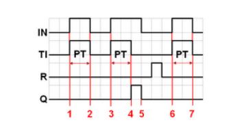
As shown in FIG:
1) When the input bit IN is set to ON, the timing bit TI is turned on, the counted time ET starts to count, and the output bit Q remains OFF.
2) When the input bit IN is set to OFF, if the counted time ET does not reach the preset time PT, the counted bit TI is turned off, and the output bit Q remains OFF. The elapsed time ET maintains the current state value.
3) When the input bit IN is set to ON again, the timing bit TI is turned on, and the elapsed time ET starts to count again from the state value just kept.
4) When the elapsed time ET is equal to the preset time PT, the timer bit TI is turned off, and the output bit Q is turned on at the same time.
5) The input bit IN is set to OFF, and the output bit Q is also turned off. (At this time, set the reset bit ON to reset the elapsed time ET to zero, and then set it to OFF.)
5. Cumulative delay switch (OFF)
Input bit (IN): Main switch of the timer.
Timing bit (TI): Set ON when timing starts.
Output bit (Q): Set to ON after the timing is over.
Preset Time (PT): Set the timer time value.
Elapsed time (ET): Displays the current elapsed time of the timer.
Reset bit (R): resets the current timer elapsed time (ET) to zero.
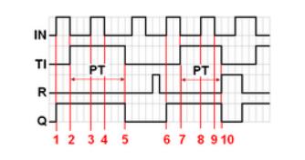
As shown in FIG:
1) When the input bit IN is set to ON, the timing bit TI remains OFF, and the output bit Q is turned on at the same time.
2) When the input bit IN is set to OFF, the timing bit TI is turned on, while the output bit Q remains ON. The elapsed time ET starts counting.
3) When the input bit IN is set to ON again, the timing bit TI and the output bit Q remain ON, and the counting time ET is suspended.
4) When the input bit IN is set to OFF again, the elapsed time ET starts to count again from the state value just held.
5) When the elapsed time ET is equal to the preset time PT, the timing bit TI and the output bit Q are turned off at the same time. (At this time, set the reset bit ON to reset the elapsed time ET to zero, and then set it to OFF.)

The size of the timer control cannot be changed, and the position can be set. When the project is running, the timer control is not displayed on the HMI.