1. Enhanced high-speed pulse counting EHCNT
1. Enhanced high-speed pulse counting EHCNT
1.1. Instruction description
| High speed counter terminal | X0 | X1 | X2 | X3 | X4 | X5 | X6 | X7 | X10 | X11 | X12 | X13 |
|---|---|---|---|---|---|---|---|---|---|---|---|---|
| single chanel counter | C235 | C236 | C237 | C238 | C239 | C240 | C241 | C242 | C243 | C244 | C245 | C246 |
| Double chanel counter | C235 | C235 | C237 | C237 | C239 | C239 | C241 | C241 | C243 | C243 | C245 | C245 |
Only multi pulse PLCs (FGm&# 95; 64MT&# 95; AC, FGm&# 95; 32MT&# 95; AC) support this function.
As shown in the table above, the high-speed counters are numbered from C235 to C246, with a total of 12 high-speed inputs. When counting single-phase, there are 12 high-speed counters, and when counting two-phase, there are a total of 6 high-speed counters.
The pulse input port is from X000 to X0013, with a maximum pulse input frequency of 1MHz and a counting range of -2147483648~+2147483647; When the count value exceeds this range, overflow or underflow phenomena will occur;
There are several counting modes for each counter, including::
| Number | Counting Mode | Single/Dual Channel |
|---|---|---|
| K0 | Single phase counting | Single channel |
| K1 | A/B phase single harmonic counting | dual channel |
| K2 | A/B phase fourth harmonic counting | dual channel |
| K3 | Single phase dual counting | Dual channel |
| K4 | Pulse direction | Dual channel |
**Single phase counting mode: * * Either counter can be selected;
A/B phase count:The default low port is phase A, and the high port is phase B. For example, A/B phase C235, X0 is connected to phase A, and X1 is connected to phase B;
Single phase dual count:The default low port input pulse count is up counting, and the high port input pulse count is down counting; For single-phase dual counting C235, X0 inputs a pulse CV235 plus 1, X1 inputs a pulse CV235 minus 1;
Pulse direction:he default low port is the pulse input port, and the high port is the direction input port. When the direction input port is OFF, it counts forward, and when it is ON, it counts backward; If the pulse direction counting is C235, X0 is connected to the pulse input, and X1 is connected to the direction input;
- There are three triggering methods for high-speed counting: self triggering, external port triggering, and cam triggering.
| Number | Trigger Method |
|---|---|
| K0 | Self triggered |
| K1 | Cam triggered |
| K2 | External trigger group 1 |
| K3 | External trigger group 2 |
① Self triggering starts counting when the counter enables conditional conduction, sets the counting flag when the target value is reached, and clears the counter value through the RST instruction.
② The external triggering method is to start and reset the counter through an external input signal. The external trigger group number and port are as follows. Firstly, to enable the counter, the pilot must be turned on. Then, the rising edge input of the port is activated to start the counter. When the rising edge input of the reset port is activated, the counter is reset. When different counters select the same external trigger group, triggering will have an effect on the already enabled counters. When the port has been used for high-speed counting external triggering, it cannot be used for other purposes.
| Group number | Startup port | Reset port |
|---|---|---|
| 1 | X25 | X26 |
| 2 | X27 | X32 |
③ Cam triggering is determined by the activation of the corresponding cam command (CAM) of the counter. Firstly, the activation of the counter must be initiated. If the activation of the corresponding cam command is activated, the counter starts counting and resets its value according to the setting of the cam command.
1.2. Attention
When using high-speed counting input or interrupt input, it is recommended to use twisted pair shielded cables for the corresponding input ports and ground the shielding layer (connected to the same terminal or signal ground) to improve anti-interference performance;
After using this type of counter, these terminals cannot be used as inputs for other counters at the same time, nor can they be used as regular input methods;
The OFF time of transistors has the characteristic of being prolonged under light loads. So, when responsiveness is required, please design a load resistor to increase the load current when the load is lighter;
After reaching the target value, the flag bit indicates real-time response and is not affected by the scanning cycle.
1.3. The valid operands of the instruction
| Input/Output | Data Type | operand | Description |
|---|---|---|---|
| CV | 32-bit Integer | CV | Counter |
| CM | 16 bit unsigned integer | K/H | Counting mode |
| TM | 16 bit unsigned integer | K/H | |
| SV | 32-bit integer | D/CV/TV/AI/AO/K/H/V/Z/FD, bit composite word (X/Y/M/C/T/S), local variable (LW) | preset value |
1.4. Example
AB phase counter (First harmonic mode):
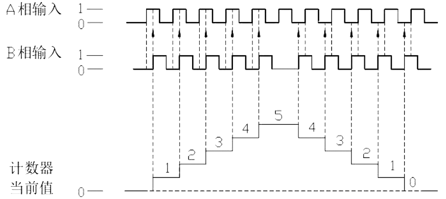
图1 frequency doubling mode
AAB phase counter (fourth harmonic mode):
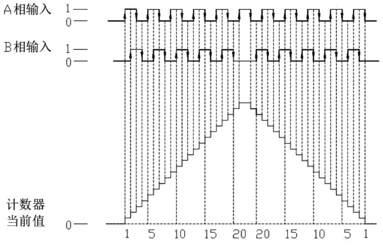
图2 fourth harmonic mode