1. High speed pulse counting HCNT
1. High speed pulse counting HCNT
1.1. Instruction description
The following is a table showing the usage of different types of PLCs and high count counters on the input end.
As shown in the table below, the high-speed counter numbers range from C235 to C254, and the pulse input ports range from X000 to X0007; Among them, U represents counting up, D represents counting down, and AB represents phase AB.
| counter type | counter number | X000 | X001 | X002 | X003 | X004 | X005 | X006 | X007 |
|---|---|---|---|---|---|---|---|---|---|
| single pahse counter | C235 | U | |||||||
| C236 | U | ||||||||
| C237 | U | ||||||||
| C238 | U | ||||||||
| C239 | U | ||||||||
| C240 | U | ||||||||
| C241 | U | ||||||||
| C242 | U | ||||||||
| single phase dual counter | C246 | U | D | ||||||
| C247 | U | D | |||||||
| C248 | U | D | |||||||
| C249 | U | D | |||||||
| A/B phase counter | C251 | A | B | ||||||
| C252 | A | B | |||||||
| C253 | A | B | |||||||
| C254 | A | B |
When an input port (e.g. X000) is used by a high-speed counter (e.g. C235), other high-speed counters (e.g. C241, C244, C246, etc.) using that input port must not appear in the ladder diagram, otherwise the high-speed counter will not function properly.
Counting range: -2147483648~+2147483647; When the count value exceeds this range, overflow or underflow phenomena will occur.
1.1.1. Attention:
When using high-speed counting input or interrupt input, it is recommended to use twisted pair shielded cables for the corresponding input ports and ground the shielding layer (connected to the same terminal or signal ground) to improve anti-interference performance;
After using this type of counter, these terminals cannot be used as inputs for other counters at the same time, nor can they be used as regular input methods;
The OFF time of transistors has the characteristic of being prolonged under light loads. So, when responsiveness is required, please design a load resistor to increase the load current when the load is lighter;
The multiplier setting for A/B phase counting is only valid before instruction initialization.
1.2. The valid operands of the instruction
| Input/Output | Data Type | operand | Description |
|---|---|---|---|
| CV | 32-bit Integer | CV | Counter |
| SV | 32-bit integer | D/CV/TV/AI/AO/K/H/V/Z/FD, bit composite word (X/Y/M/C/T/S), local variable (LW) | preset value |
1.3. Example 1 Single phase counter without startup/reset
Command table:
NETWORK 000
LD M8035
OUT Y000
NETWORK 001
LD M0
HCNT CV235 K1000 // When M0 is' 1 'and M8035 is' 0', CV235 counts the input pulses of X000 in the forward direction. When the count reaches 1000, set C235
NETWORK 002
LD C235
OUT Y001
NETWORK 003
LDP M1
RST C235 K1 // When the rising edge of M1 approaches, reset C235 and CV235 to zero
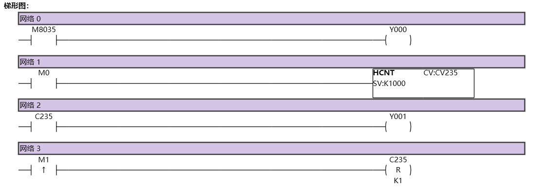
图1 HCNT11
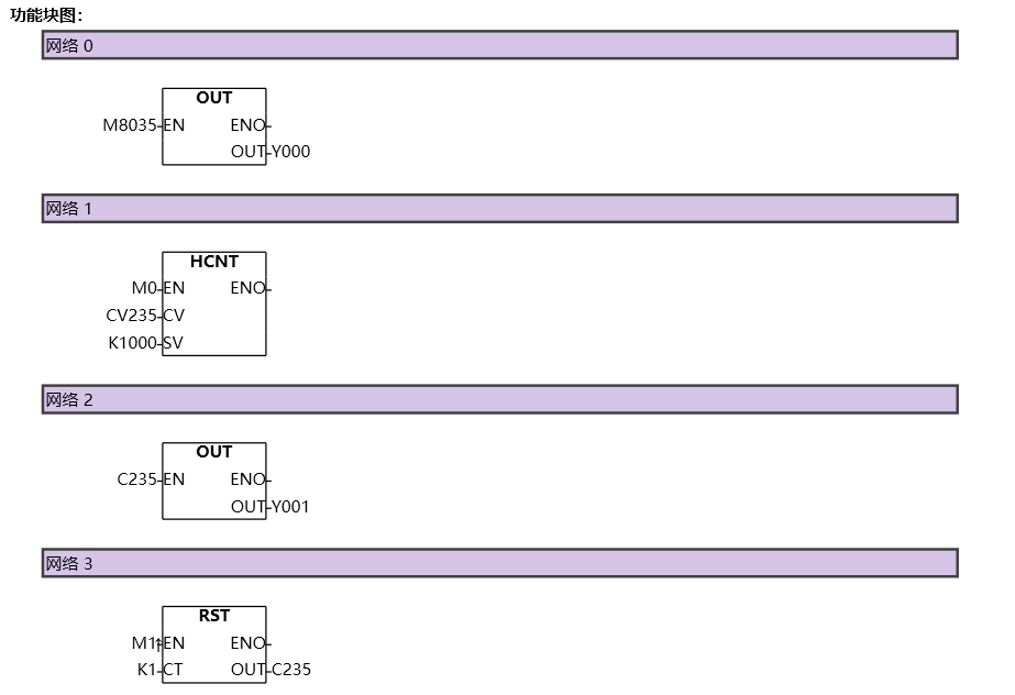
图2 HCNT12
1.4. Example 2. Single phase dual counter
Command table:
NETWORK 000
LD M0
HCNT CV249 K1000
NETWORK 001
LD C249
OUT Y001
NETWORK 002
LDP M1
RST C249 K1
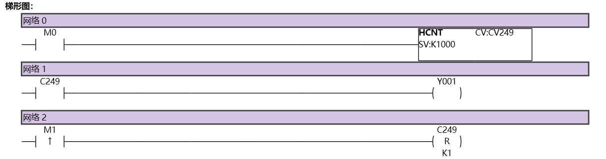
图3 HCNT21
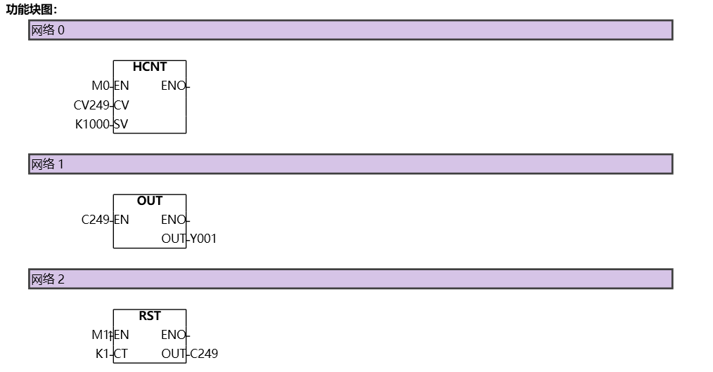
图4 HCNT22
1.5. Example 3. AB phase counter
The AB phase counter is divided into two counting modes, which are controlled by M8051~M8054 to control the AB phase counter C251~C254 frequency doubling mode. When the corresponding M is' 0 ', it is the first frequency doubling mode. When set to '1', it is in quadruple mode, and the setting of the multiplier should be done before the counter initialization, as shown in the following figure:
AB phase counter(First harmonic mode):
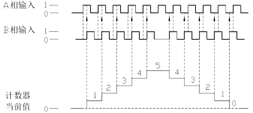
图5 First harmonic mode
AB phase counter (fourth harmonic mode):
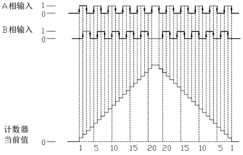
图6 fourth harmonic mode
Command table:
NETWORK 000
LD M0
HCNT CV251 K1000
NETWORK 001
LD C251
OUT Y001
NETWORK 002
LDP M1
RST C251 K1
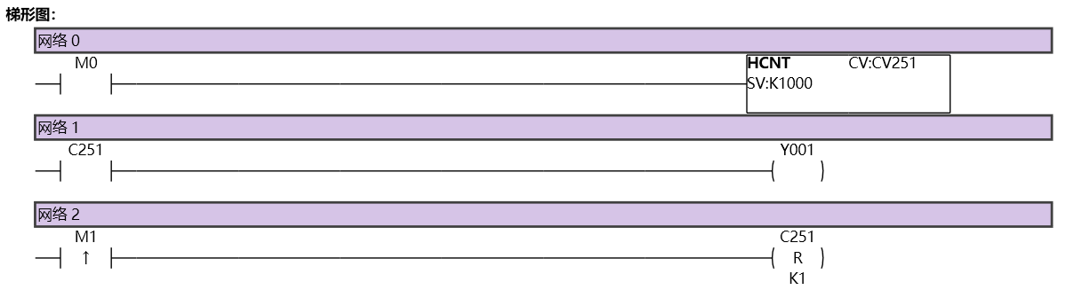
图7 HCNT31
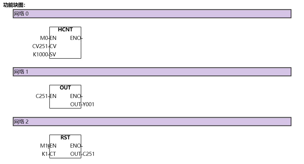
图8 HCNT32