1. Pulse density measurement SPD
1. Pulse density measurement SPD
1.1. Instruction Description
he instruction counts the high-speed input pulses within a specified time and stores the result in a set register. The measurement result of this instruction will occupy six consecutive D registers. The instruction saves the number of pulses recorded during the measurement period to the D register (32-bit), saves the number of pulses recorded during the current measurement cycle to the D+2 register (32-bit), and saves the remaining time of the current measurement cycle to the D+4 register (32-bit).
For model GT-043-MT, the available pulse input ports are X000~X001, and the maximum supported pulse input frequency is 200KHz; For model GT-070-32MT, FAs-32MT-AC, FAs-50MT-AC, FAs-66MT-AC, The available pulse input ports are X000~X003, and the maximum supported pulse input frequency is 200KHz;
When a certain input port (e.g. X000) is used and enabled by a certain pulse density measurement instruction, the high-speed counter of that input port (e.g. C235, C241, C244, C246, etc.) cannot be enabled at the same time, otherwise the high-speed counter will not work properly. Each input point can only use one pulse density measurement instruction
Attention:
After using this instruction, these terminals cannot be used as inputs for other counters at the same time, cannot be used as external interrupts, and cannot be used as normal input methods;
When the command is enabled and the measurement time value is changed, the current speed measurement cycle value will not be updated immediately. Instead, a speed measurement will be completed based on the previous measurement time and will take effect from the next measurement cycle;
When using high-speed counting input or interrupt input, it is recommended to use twisted pair shielded cables for the corresponding input ports and ground the shielding layer (connected to the same terminal or signal ground) to improve anti-interference performance;
The OFF time of transistors has the characteristic of being prolonged under light loads. So when responsiveness is needed, please design a load resistor to increase the load current when the load is lighter
1.2. The valid operands of the instruction
| Input/Output | Data Type | operand | Description |
|---|---|---|---|
| X | ON/OFF | X | Input |
| T | 32-bit integer | D/CV/K/H/FD, bit composite word (X/Y/M/C/T/S), local variable (LD) | measurement time |
| OUT | 32-bit integer | D/CV, bit composite word (Y/M/C/T/S), local variable (LD) | output |
1.3. Example
command table:
NETWORK 000
LD M000
SPD X000 D0 D2 //Measure the number of pulses at port X0 within D0 milliseconds and save the result to D2. The number of pulses recorded in the current measurement cycle is saved to D4, and the remaining time of the current measurement cycle is saved to D6
POP
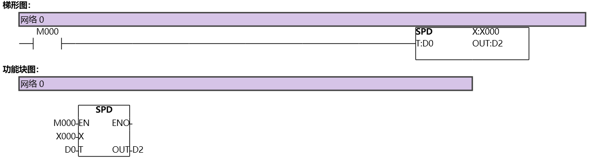
图1 SPD