1. High speed counting target value interrupt event HSCS
1. High speed counting target value interrupt event HSCS
1.1. Instruction Description
At present, this command supports the following models:
(
)
The HSCS instruction is used in conjunction with single-phase high-speed counters (such as CV235, CV236, etc.) or AB phase high-speed counters (CV251), and the corresponding HCNT high-speed counter must be connected before the HSCS instruction can be activated;
After disabling this instruction, it will not trigger an interrupt program. If the high-speed count value does not exceed the next interrupt target value, it can continue to trigger after reconnecting. If the next interrupt target value is exceeded, subsequent interrupt operations cannot be triggered (when AB is reversed and passes the next target value, all subsequent interrupts can still be triggered at once);
When the RST instruction is used to reset the flag of the corresponding high-speed counter (such as CV235, CV251), clearing the high-speed counter count value will initialize the target value interrupt function, and the preset target value interrupt event will be triggered again from the first segment;
Interrupt events are implemented immediately within the interrupt and are independent of the scanning cycle.
1.2. Parameter settings
The parameter setting interface is as follows:
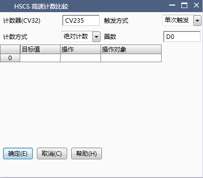
图1 HSCS
Counter (CV32): Enter the number of the high-speed counter, single-phase high-speed counters CV235~CV238, AB phase high-speed counters CV251~CV252. (Currently does not support bidirectional counters)
Trigger mode and number of turns: There are two types of trigger modes: loop trigger and single trigger. In loop trigger mode, a dual word D register can be specified to display the number of loops.
Loop Trigger: When the count value reaches the last target value and triggers the corresponding interrupt program, the current counter value will reset to zero and restart counting. At the same time, the number of cycles will increase by 1, and the interrupt event will be triggered from the first segment according to the preset target value.
Single trigger: When the count value reaches the last target value and triggers the corresponding interrupt program, the current counter value will continue to count. If the counter is not reset, the interrupt will not be triggered again.
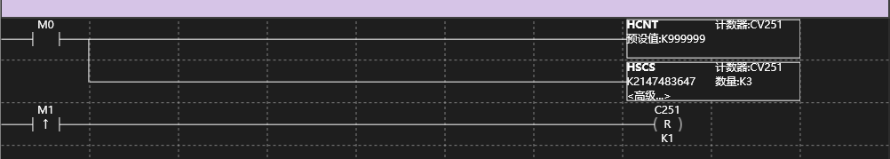
图2 HSCS
Tips:
Interrupt triggers are executed sequentially according to the pre-set interrupt target values, and no other target value interrupts will be triggered until the interrupt event corresponding to the next target value is triggered
Counting mode: Counting mode is divided into absolute mode and relative mode
Absolute mode: The target value represents the actual count that triggers an interrupt when the target value is reached. As shown in the parameter setting interface, when the high-speed counter CV235 reaches 1000, 2000, and 3000 respectively, it will trigger the corresponding interrupt event.
Relative Mode: The target value represents the interrupt event triggered when the count reaches the previous target value plus the increased count value in this segment. As shown in the parameter settings interface, the corresponding interrupt event is triggered when the high-speed counter CV235 reaches 1000, 1000+2000=3000, and 3000+3000=6000, respectively.
Target value: The target value can be of two types: K (double word constant) and D (double word register). In the parameter setting interface, the target value can be increased in batches by setting incremental values. During the operation, the target value can be increased or modified individually or in batches. It is also possible to move a target value up or down, but it should be noted that certain conditions must be met between the target values to take effect.
Tips:
In absolute mode, the target value of the single-phase high-speed counter must be greater than the target value of the previous segment, and the target value of the AB phase high-speed counter is not equal to the target value of the previous segment.
In relative mode, the target value of the single-phase high-speed counter must be greater than 0, and the target value of the AB phase high-speed counter is not equal to 0.
Regardless of the mode, the target value of the single-phase high-speed counter cannot be set to a negative value, while the AB phase can be set to a negative value.值。
The first target value cannot be 0
If the target value of this paragraph does not meet the above conditions, the interrupt event corresponding to the target value of this paragraph will not be triggered, and subsequent events will still be triggered in sequence.
The interval between target values is recommended to be greater than or equal to 50, otherwise it may not be possible to enter the interrupt normally during high-frequency counting.
Interrupt program: Interrupt events are divided into setting a certain coil, resetting a certain coil, executing a certain interrupt subroutine, which can be set under the interrupt program column of the target value in the parameter interface
Set coil: Input # (SET M10) represents set coil M10, and input # (SET Y003) represents set output Y003.
Reset coil: Input # (RST M10) represents reset coil M10, and input # (RST Y003) represents reset output Y003.
Interrupt subroutine: Create subroutine t1 in the ladder diagram and enter t1 at the corresponding position
Empty: No input, there will be no operation when the count reaches the target value at that location
Tips:
At present, only M and Y type registers are supported for input, and Y does not include the range of expansion modules.
You need to first create an interrupt subroutine in the ladder diagram, and then enter the name of the interrupt subroutine in the target value.
The target value corresponding to the null operation can be used as the maximum count value in the loop mode, and when the count reaches this value, it will automatically loop.
Table length: The restructuring will automatically display how many target values have been created in total, with a maximum limit of 100 target value segments.
1.3. LAD example
Command table:
NETWORK 000
LD M0
HCNT CV251 K999999
POP
LD M1
HSCS CV235 K2147483647 K0
POP
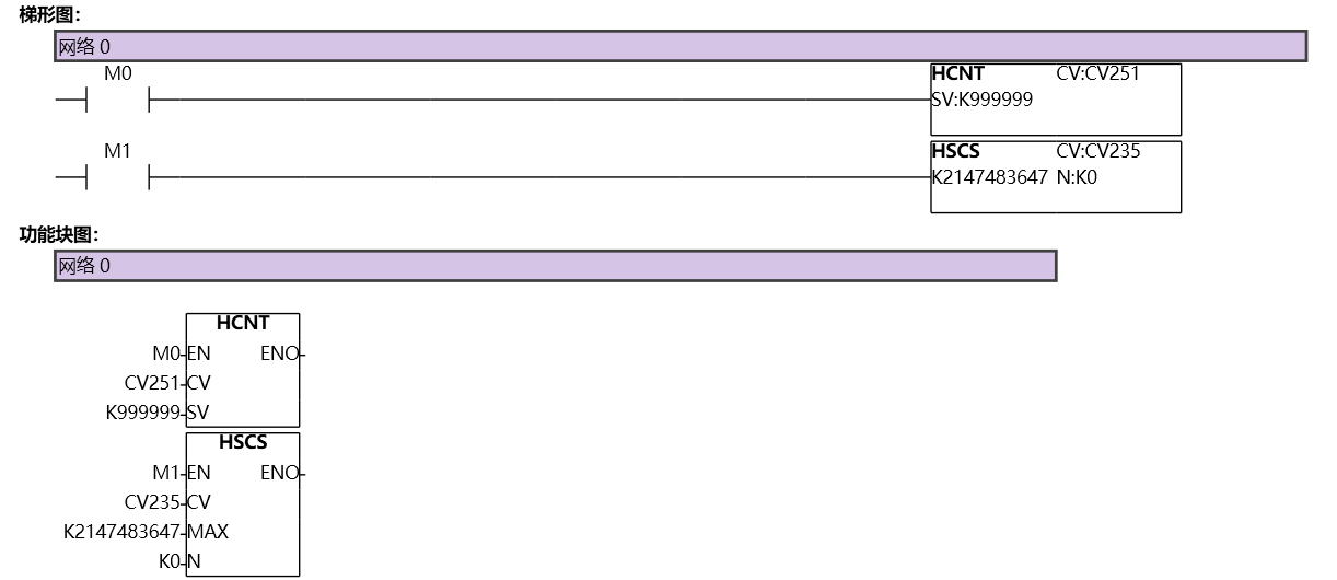
图3 HSCS
Example Description: When M0 is set, the high-speed counter is turned on while the target value interrupt instruction HSCS is turned on. In this example, the AB phase high-speed counter CV251 is turned on. At the same time, when M1 rises, the high-speed counter and the target value interrupt instruction HSCS are reset, counting starts from zero, and the target value interrupt is triggered again from the first segment.
Tips:
The loop mode cycle number recording register will not automatically reset, and the user needs to manually reset the counter when resetting it