Circle/Ellipse
Select the Circle/Ellipse
command in the Draw menu or left-click the Circle/Ellipse command
button![]() in the toolbar. Move
the mouse to the screen editing window, and the mouse cursor will become a
cross; click the left mouse button on the screen to add a circle to the screen.
in the toolbar. Move
the mouse to the screen editing window, and the mouse cursor will become a
cross; click the left mouse button on the screen to add a circle to the screen.
To change the size
of an ellipse / circle, select the Circle/Ellipse first, then move the mouse to the 8 square green dots that appear
in the ellipse / circle. When the mouse cursor becomes ![]() or
or ![]() or
or![]() , click and hold down the left mouse button to an appropriate
location; release the left button to complete drawing.
, click and hold down the left mouse button to an appropriate
location; release the left button to complete drawing.
![]() :Change the width of the ellipse / circle
:Change the width of the ellipse / circle
![]() :Change the height of the ellipse / circle
:Change the height of the ellipse / circle
![]() :Change the width and
height of the ellipse / circle
:Change the width and
height of the ellipse / circle
After the above
steps, the transparency, line type, line width, line color, and fill pattern of
the ellipse / circle will be set by default. The engineer can modify these
attributes to meet the needs of the project. Move the cursor to the ellipse /
circle, double click the left button; or select the Circle/Ellipse first, and
then click the Property button ![]() in the toolbar, here a
dialog box will pop up.
in the toolbar, here a
dialog box will pop up.
The SKTOOL configuration software provides up to 15 types of border line, 10 kinds of border line width and 21 of fill patterns for ellipse / circle. As shown in Figure 4-32:
Figure4-32 Circle/Ellipse
Dynamic Color
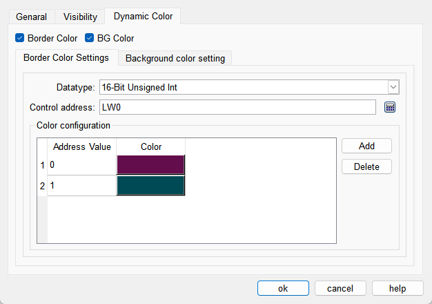
The colors of border and background can be changed by modifying the values of the corresponding registers. You need to check the corresponding option to enable the dynamic color function.
l Data Type: Set the data type of the register.
l Control Address: Set the address of the register that controls color changes.
l Color Configuration: Multiple values and their corresponding colors can be configured. When the value of the register corresponding to the control address matches one of the configured values, the corresponding color will be displayed. (If the register value does not match any of the configured values, the color set in the configuration will be displayed.)