Curve / Arc
Select the Curve /
Arc command in the Draw menu or click the Curve / Arc command button ![]() in the toolbar menu; move the mouse to the Edit window, then the
mouse cursor will change to a cross, by now you can draw a curve / arc in the
Edit Window.
in the toolbar menu; move the mouse to the Edit window, then the
mouse cursor will change to a cross, by now you can draw a curve / arc in the
Edit Window.
Move the mouse to a position where you want to curve. Left click and a small green dot appears in the window. This position is the start position of the curve / arc.
Move the mouse to other position in the screen, then the system will automatically draw a straight line; after click the left mouse button and release.
At this time, the mouse cursor is still cross-shaped. Move the mouse to other position in the screen, which is the end of the curve / arc. Hold down the left button does and move the mouse in the screen to draw the arc; release the mouse and right click to end the operation. As shown in Figure 4-26:
Figure4-26 Curve Operation
As shown above, the starting point of the graph is a green dot, and
the end point is a diamond dot, here the initial curve / arc has
been drawn. Move the mouse to the point and the cursor becomes the shape of ![]() ; hold down the left mouse button, move the mouse to the appropriate
location, and then release the mouse to draw the required curve. You can also
move the start or end point to the appropriate position. As shown in Figure 4-27:
; hold down the left mouse button, move the mouse to the appropriate
location, and then release the mouse to draw the required curve. You can also
move the start or end point to the appropriate position. As shown in Figure 4-27:
Figure4-27 Curve Operation
After completing the above steps, the transparency, line type, line
width, line color, end point and endpoint shape of the curve / arc will be set by
the system default. The engineer can modify these attributes to meet the
requirement of engineering. Move the mouse to the curve / arc; double-click the
left button, or select the curve / arc first, and then click the toolbar
property button![]() , a dialog box same as that of Line Property will pop
up.
, a dialog box same as that of Line Property will pop
up.
You can adjust the curve / arc properties through the pull-down and trimming buttons. The SKTOOL configuration software provides up to 15 line types, 10 kinds of line widths, and 6 straight-line end arrows for curves / arcs.
Dynamic Color
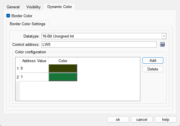
The color of border can be changed by modifying the values of the corresponding registers. You need to check the corresponding option to enable the dynamic color function.
l Data Type: Set the data type of the register.
l Control Address: Set the address of the register that controls color changes.
l Color Configuration: Multiple values and their corresponding colors can be configured. When the value of the register corresponding to the control address matches one of the configured values, the corresponding color will be displayed. (If the register value does not match any of the configured values, the color set in the configuration will be displayed.)