RoundRect
Choose the ![]() icon from Basic Graphs in
the control bar, move the cursor to editing area, and the cursor will become a
cross.
icon from Basic Graphs in
the control bar, move the cursor to editing area, and the cursor will become a
cross.
Click the starting position where the graph will be placed, drag the cursor when pressing the mouse key. At this moment the system will automatically draw an area along the track of the cursor. Then, click left or right mouse key to complete drawing of rectangle.
![]() :
Change the width of the rounded rectangle
:
Change the width of the rounded rectangle
![]() : Change the height of the rounded rectangle
: Change the height of the rounded rectangle
![]() :
Change the width and height of the rounded rectangle
:
Change the width and height of the rounded rectangle
After
the above steps, the transparency, line type, line width, line color and fill
pattern of the rounded rectangle will be set by the system default. The
engineer can modify these properties to meet the needs of the project. Move the
mouse on it, double click the left button; or select the rounded rectangle
first, and then click the Property button![]() in the toolbar. The
properties of the rectangle will pop up, as shown in Figure 4-31
in the toolbar. The
properties of the rectangle will pop up, as shown in Figure 4-31
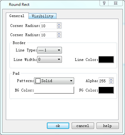
Figure 4-31 Rectangle properties dialog
Radius of X curve: Radian of the four corners in X direction.
Radius of Y curve: Radian of the four corners in Y direction.
Dynamic Color
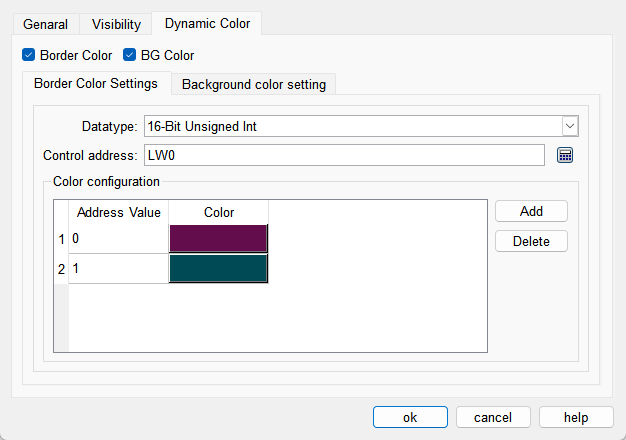
The colors of border and background can be changed by modifying the values of the corresponding registers. You need to check the corresponding option to enable the dynamic color function.
l Data Type: Set the data type of the register.
l Control Address: Set the address of the register that controls color changes.
l Color Configuration: Multiple values and their corresponding colors can be configured. When the value of the register corresponding to the control address matches one of the configured values, the corresponding color will be displayed. (If the register value does not match any of the configured values, the color set in the configuration will be displayed.)