Polygon
Select the Polygon command in the Draw menu
or click the Polygon command button ![]() in the toolbar. Move the mouse to the editting
window. The mouse will change to a cross, by now you can draw a polygon in the
screen.
in the toolbar. Move the mouse to the editting
window. The mouse will change to a cross, by now you can draw a polygon in the
screen.
Move the mouse to a position where you want to draw a polygon, left click (or hold down the left button), then a small green dot will appear in the screen editing window, which is the start point of the polygon.
Move the mouse to another position on the screen. At this time, the system will draw a straight line automatically. Move the mouse to other appropriate positions; each time you left click, a new side of polygon is drawed; right click to complete drawing. As shown in Figure 4-33:
Figure 4-33 Polygon Operation
To re-shape a polygon, click it first and it
will appear several green dots (depending on the number of sides of the
polygon), indicating that the polygon has been selected; and then move the
mouse cursor over one of them, then it will become the shape ![]() ; left click and drag it to the position you prefer, so that you can
change the length and location of two lines connected by this turning point.
Release the left button to complete.
; left click and drag it to the position you prefer, so that you can
change the length and location of two lines connected by this turning point.
Release the left button to complete.
After the above steps, the transparency,
line type, line width, line color and fill pattern of the polygon will be set
by the system default. The engineer can modify these attributes to meet the
needs of the project. Move the mouse over the polygon, double click the left
mouse button; or select the polygon first, and then click the Property button![]() in the toolbar, and a dialog box same as that of the rectangle will
pop up.
in the toolbar, and a dialog box same as that of the rectangle will
pop up.
You can adjust the properties of polygon through the pull-down and fine-tuning buttons. SKTOOL configuration software provides up to 15 types of border line, 10 kinds of border line width and 21 kinds of fill patterns for the polygon.As shown in Figure 4-34:
Figure 4-34 Polygon
Dynamic Color
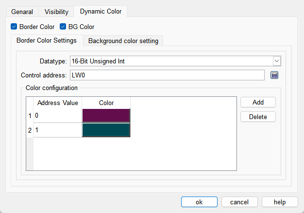
The colors of border and background can be changed by modifying the values of the corresponding registers. You need to check the corresponding option to enable the dynamic color function.
l Data Type: Set the data type of the register.
l Control Address: Set the address of the register that controls color changes.
l Color Configuration: Multiple values and their corresponding colors can be configured. When the value of the register corresponding to the control address matches one of the configured values, the corresponding color will be displayed. (If the register value does not match any of the configured values, the color set in the configuration will be displayed.)