Communication Port Property
Communication port property is applied to set the communication parameters between HMI and connected devices. HMIs like SK-121F,SK-104F,SK-102H,SK-102C,SK-070G,SK-070M,SK-070F,SK-070H are equipped with two communication ports, COM1 and COM2, supporting simultaneous communication with two different PLCs; and parameters of each port must be set. HMIs like SK-050H,SK-043U,SK-043F,SK-043H, SK-035U,SK-035F have one communication port, COM1, and it communicate only with one connected device.
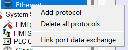
Ø The communication interface supports multiple protocols, and each interface connection can mount multiple protocols. Support protocol migration (connection port COM port or Ethernet port protocol exchange). as the picture shows.
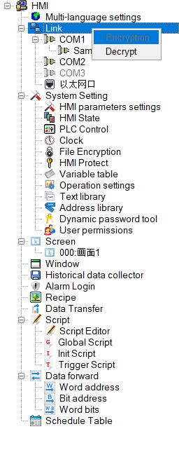
Ø Encryption/decryption. Right-click the connection and select Encryption. After encryption, the protocol node cannot be modified and needs to be decrypted before modification.

Capacity limitation: The serial port can only establish one set of protocols; the Ethernet port can have multiple groups (up to 64 groups).
Import communication tags: Support AB, OMRON, SIEMENS, MATSUSHITA, CodeSys, HollySys Group and other tag communication
Double click "Link" and " Link 1", as shown in Figure 7-1:
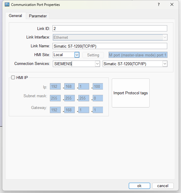
Figure 7-1 COM1 COM port property dialog box
In the "Link" page, various brands and models of PLC are available. In addition, the "Link name" and "PLC consecutive address interval"
Click the Parameter tab of the dialog box, as shown in Figure 7-2:
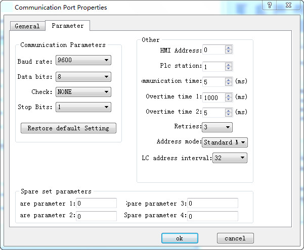
Figure 7-2 COM1 Communication port parameter setting
Parameter settings:
Equipment services: manufacturer, PLC brand and CPU model.
Port: RS232 / 485/ 422
Baud rate: 1200/2400/4800/9600/19200/38400/57600/115200 / 187.5k
Check: Odd / Even / None
Data bits: 7/8
Stop bits: 1/2
Model: PLC model
HMI station number: Set the station number of the HMI
Communication time: HMI sends data to the PLC and receives the data from PLC, and it cannot send data again until after the set communication time.
Overtime time 1 and Overtime time 2: Calculate first the value of Timeout 1 divided by that of Timeout 2, as shown in the figure above: the timeout period is 200ms. There is a situation called timeout if the HMI has not received the data 200ms after sending data.
Number of retries: The number of times that the data is retransmitted after a timeout
Address mode: ① Standard mode: One serial port connects one PLC; ② Extended mode: One serial port connects multiple PLCs of the same type
PLC Continuous Address Interval: The maximum number of words that PLC can read at one time