1. Falling edge contact LDF
1. Falling edge contact LDF
1.1. Instruction Description
1) When a negative jump (on/off) is detected in the specified bit, the contact closes for one scanning cycle;
2) For the falling edge instruction, the specified bit contact allows the stack top value to be set to 1 each time a 1 to 0 (ON → OFF) transition is performed during a scan; Otherwise, set it to 0;
3) The instruction is executed for only one moment at a time (PLC scanning cycle). Commonly used for signal triggering in sequential control, cannot be used as an output (external coils may not absorb, this should be noted);
4) Special attention should be paid when using this instruction, as the contacts will only be connected when the system detects a change in the falling edge. Improper handling during actual use may result in missing the opportunity and prevent it from happening.
1.2. The valid operands of the instruction
| Input/Output | Data Type | operand | Description |
|---|---|---|---|
| IN | ON/OFF | X/Y/M/C/T/S, word to Bit(D/V/Z), local variable(LB) | input |
1.3. Example
Instruction table:
NETWORK 000
LD X000 // Load input coil X000, X000 must be equal to 1 to activate X000
OR X002 // Perform an 'OR' operation with input coil X002
ANDF X001 // Perform 'AND' operation with input coil X001
SET Y000 K1 // Output coil Y000
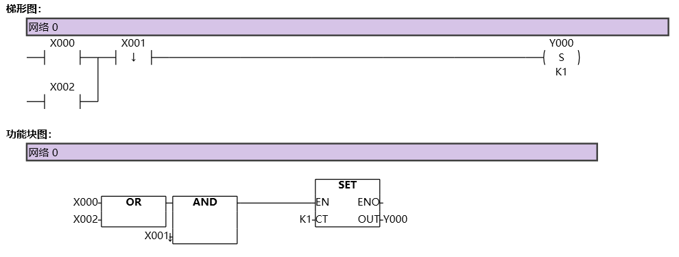
图1 LDF