1. Non rising edge contact LDPI
1. Non rising edge contact LDPI
1.1. Instruction Description
1) When a positive transition (disconnection to continuity) is detected in the specified bit, the contact opens for one scanning cycle.
2) For non rising edge instructions, the specified bit allows the stack top value to be set to 0 each time when 0 to 1 (OFF → ON) transition is performed during a scan; Otherwise, set it to 1;
3) The instruction will continue to execute unless a specified bit detects a positive jump, and the instruction will only disconnect for a moment (PLC scan cycle). Commonly used for signal triggering in sequential control, cannot be used as an output (external coils may not absorb, this should be noted);
4) Special attention should be paid when using this instruction, as the contact will only open when the system detects a change in the rising edge. Improper handling during actual use may result in missing the opportunity and prevent it from happening.
1.2. The valid operands of the instruction
| Input/Output | Data Type | operand | Description |
|---|---|---|---|
| IN | ON/OFF | X/Y/M/C/T/S, word to Bit(D/V/Z), Local variable(LB) | input |
1.3. Example
Instruction table:
NETWORK 000
LDPI X000
AND X001
OUT Y000
POP
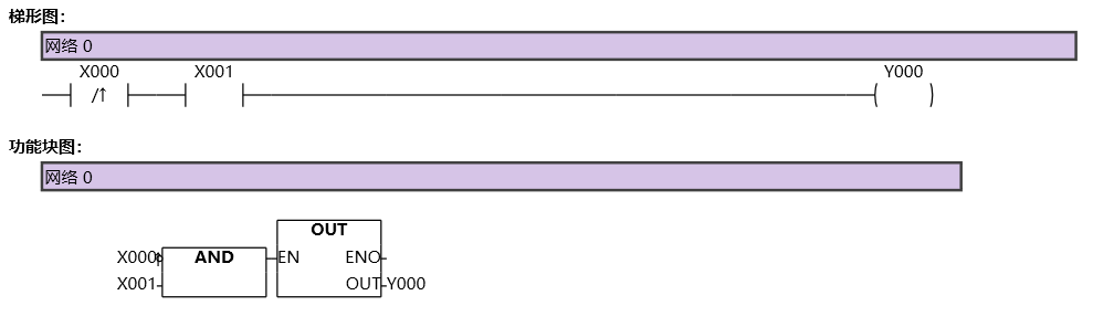
图1 LDPI