1. Decoding DECO
1. Decoding DECO
1.1. Instruction Description
The DECO instruction treats the input (IN) value as an offset address, adds the output address (OUT) to the position where this offset address is located, and sets all other positions to OFF.
Only take the first n bits of the input value as the offset address, where n ranges from 1 to 8. The length of the range where the output address starts to be affected is 2 to the power of n.
For example, in DECO K22 M10 K3, the input value is 22, n is 3, and the nth power of 2 is 8, affecting the output address M [10.. 17]. Although the input value is 22, only the first 3 bits of its binary, which is 6, are taken as the offset address. M [10+6] means M16 is set to ON and all other areas are cleared.
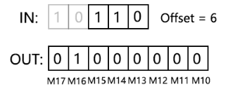
图1 解码
1.2. The valid operands of the instruction
1.2.1. Decoding (DECO)
| Input/Output | Data Type | operand | Description |
|---|---|---|---|
| IN | 16 bit integer | D/CV/TV/AI/AO/K/H/V/Z/FD, bit composite word (X/Y/M/C/T/S), local variable (LW) | Input |
| OUT | ON/OFF | Y/M/S, word positioning (D/V/Z) | Output |
| N | 16 bit integer | D/CV/TV/AI/AO/K/H/V/Z/FD, bit composite word (X/Y/M/C/T/S), local variable (LW) | quantity |
1.3. Example
Command table:
NETWORK 000
LDP X020
DECO K4X0 M10 K3 // Combine X0X1X2X3 into a 4-bit integer, take the first 3 bits X0X1X2, and use them as offset addresses to process M [10... 17].
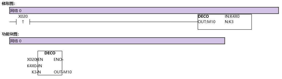
图2 DECO