1. Software Component Manager
1. Software Component Manager
The software component manager allows for the assignment of symbol names and description comments for software components. The defined symbols apply globally. Defined symbols can be used in all Program Organization Units (POUs) of a program.
if Program Parameter Tablethe parameter variable is applicable to the local scope. It only applies to the program in which it is defined, and differs from symbols that apply globally.
if the program difine local value variable局部变量,then only the local range is used
If the program parameters have the same name as the global symbol, the program parameters take precedence. Local variables have higher priority* So it is strongly not recommended to engage in such behavior*
Symbols and annotations can be defined before or after creating program logic.
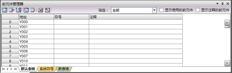
图1 Software Component Manager
1.1. Open the window
To view the Engineering Explorer (if not displayed), please follow these steps:
Click the down arrow under the Window button in the Windows section of the View menu.
Click on 'Element manager' in the drop-down menu.
1.2. Default Table
List all software components that are currently in use or have been used.
*The software component being used will be saved and closed before reopening, and will still be retained in the default table.
*Used software components, if there are defined symbols or comments, will be retained in the default table after saving and closing and reopening.
*Used software components with empty symbols and annotations will be lost in the default table if saved and closed before opening again.
1.3. System symbol
List specialized software components for PLC systems* These types of software components have clear functions and cannot be used for other purposes*
1.4. New Table (General Table)
After creating the project, a new table is automatically added.
*You can add, rename, or delete any of these tables.
*Software components can be added and removed freely in this table, without affecting the properties and program logic of the software components themselves.
1.5. Function buttons
The function buttons are arranged on the top left side, listed from left to right as follows.
| Icon | Name | Function |
|---|---|---|
 |
new table | Create a new generic table.。 |
 |
Insert row | Insert a new row at the selected location.。 |
 |
Guide | Guide to Implement More Operations。 |
 |
Delete table | Delete the currently open generic table, note that default tables and system symbols cannot be deleted. |
 |
Delete Row | Delete the row where the selected position is located. |
 |
import | Import external data into the software component manager. |
 |
Export | Export the current table as external data. |
1.6. Filter
Set a filtering type to display only software components of this type.。
1.7. Display the software components used
Check this option to display only the software components used by the program.
1.8. Software components displaying annotations
Check this option to display only software components with annotations.