1. SDO-MODBUS master communication SDO-MODBUS
1. SDO-MODBUS master communication SDO-MODBUS
1.1. PLC mode
a) S-8X8T: 8 digital input, 8 digital output,DC24V power supply, RS485 communication, USB port, CAN communication, 4-channel high-speed pulse output, 2-channel hardware high-speed counting, 2-channel software high-speed counting.
b) S-8X8T_C: 8 digital input, 8 digital output,DC24V power supply, CAN communication, USB port, CAN communication, 4-channel high-speed pulse output, 2-channel hardware high-speed counting, and 2-channel software high-speed counting.
c) S_16T: 16 digital output, DC24V power supply, RS485 communication,USB port, CAN communication, 4-channel high-speed pulse output, 2-channel hardware high-speed counting, 2-channel software high-speed counting.
d) S16TC: 16digital output, DC24V power supply, CAN communication, USB communication, CAN communication , 4 high-speed pulse outputs, 2 hardware high-speed counts, and 2 software high-speed counts.
1.2. CAN connection configure
a) When using the S series PLC as an expansion module, the supported CPU types include: FAs-32MT-AC, FAs-50MT-AC,FAs-66MT-AC,FAt-16MT-DC, Note that there can only be one CPU(master) in a network, and supports up to 16 slaves.
b) The module uses a CAN communicate with the CPU, supporting side direct insertion or terminal remote wired. When connecting through direct insertion, it is recommended to set rate more than 100kbps to improve communication speed. When wiring each other, the distance up to 25m, it is recommended to set rate less than 500kbps, choice thicker shielded twisted pair cables frist ; Connect a 100Ω resistor to the bus terminal (it can be connected between the top two pins or bottom two pins of the side plug port, and there is also an optional termination resistor plug-in, attention a arrow pointing upwards).
c) Module CAN settings
i. Select "Project Settings" under "Config" in the menu bar
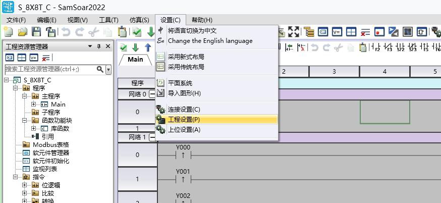
图1 SDO2.1
ii. Select the module in the pop-up project settings window
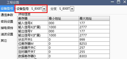
图2 SDO2.2
iii. Select the "Communication" tab on the left and configure the node ID and baud rate under the CAN tab. The filtering settings at the "Filtering Settings" tab below is very important: the node ID will correspond to the X/Y shift address at the CPU configuration, no business where the CAN network location, rather than automatically numbering based on the insertion position like the previous expansion module;use the same baud rate in the same CAN network, otherwise it will not only fail to connect to the CPU but also cause interference to all modules.

图3 SDO2.3
iv. Check configuration and initialization, download project
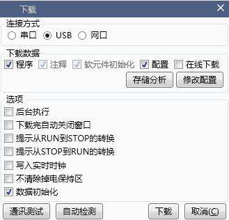
图4 SDO2.4
d) d) CPU CAN settings
i. i. Set the CPU model, node ID, and baud rate as in 2-c-i, ii, and iii
ii. Select the Expansion tab on the left,and select “Used expansion module” option
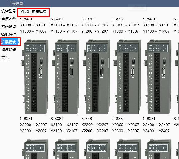
图5 SDO2.5
iii. Add modules, match node ID and corresponding registers (module baud rate and filtering time are currently set in the “communication” tab), and support up to 16 S-series PLCs as expansion modules.
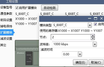
图6 SDO2.6
iv. Check configuration and initialization, download project
1.3. Software features
a) All modules configured in step “d)iii” will be verified when CPU power on. If the verification fails, another reconnection attempt will be made. The special register single word D8190 records the attempt result, and each bit from low to high represents the reconnection status of the 1st to 16th modules. The station value failed will be set to 1; The special register single word D8191 records the current communication status of all modules, timeout of “0”, online “1”.
b) The special register single word D8192 records the node ID of itself; The single word D8193 records the baud rate (Kbps) of itself; The single word D8189 indicates the current load situation of the CANbus. When approaching or exceeding 100, nodes ID with high load and lower priority may not be able to communicate. In this case, set higher baud rates or reduce the frequency of IO conversion.
c) When using the S series PLC as an expansion module, the output is controlled by the CPU, cannot be forced or controlled by using a ladder program, otherwise an error 124 will be reported in single word D8176; When the module needs autonomous control, a special register M8000 can be set. At this time, the output order transmitted by the CPU is no longer working derectly, but the Y state is stored in the module's single word D8000 from low to high. At the same time, the CPU's X1000-X1007 (to X2700-X2707) is no longer directly transmitted by the slave's X, but is read from the slave's D8016.
d) When using high-speed output, it is also necessary to set the M8000 of the module. At this time, D8000 and D8016 can be used to automatically interact with the CPU for a small amount of data and logic at high speed. Y1000-Y1017 to Y1040-Y1057 of the CPU will be directly mapped to D8000 to D8002 of the slave through PDO, and D8016 to D8018 of the slave will be mapped to X1000-X1017 to X1040-X1057 of the CPU. If M8000 is reset, it is equivalent to resetting all pulse instructions; Especially, if only need an independent high-speed output port, other outputs are still controlled by the CPU, we could set register M8001 .
e) CAN is suitable for fast transmission of small amounts of data, so only the IO data carried between the module and the CPU automatic. If other registers need to be read or configured, the software provides a custom protocol interface SDO-MODBUS instruction:
i. In the Project window, we can create a new SDO-MODBUS table, fill in the table ID and several pieces of data that need to be communicated. The index of the slave register refers to the setting of the Modbus address shift table
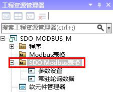
图7 SDO3.1
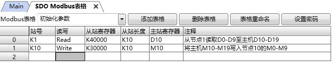
图8 SDO3.2
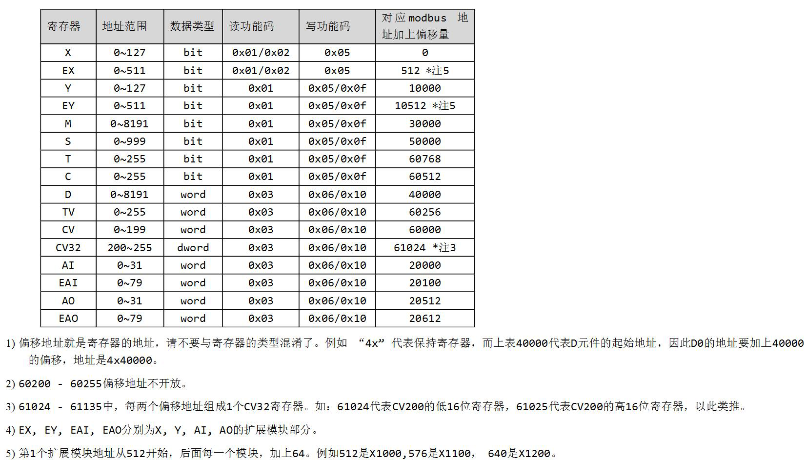
图9 SDO3.3
1)The shift address is the register address, please do not mess it with the register type. For example, "4X" represents a holding register. And the table above shows the starting address of D register, so the address of D0 needs to be shift by 40000, which is 4X4000
2)60200-60255 shift address are not open
3)From 61024 to 61135, every two shift addresses form one CV3 register. For example, 61024 represents the low 16 bit register of CV200, and 61025 represents the high 16 bit register of CV200.
4)EX,EY,EAI,EAO represent each part of expansion X,Y,AI,AO
The frist expansion module adress begin at 512, when add one more, add 64, for example, 512 represent X1000, 576 represent X1100, 640 represent X1200.
ii. Add the SDO-MODBUS instruction to the ladder diagram, select the corresponding table and fill in the indicator registers for the MODBUS index being sent and received (16 bits), the MODBUS index with exceptions (16 bits), and the return code (32 bits) in sequence. The default value for the first two is 0xFFFF. When polling to this instruction, it will indicate the current sending status, and the default value for the return code is 0xFFFFFF. After successfully completing all the sending and receiving of the table corresponding to this instruction once, it will return 0 (hold for 10ms) until the next polling to this instruction or an error returns other error codes (see subsequent 3-f: SDO-READ/WRITE instructions for details)。
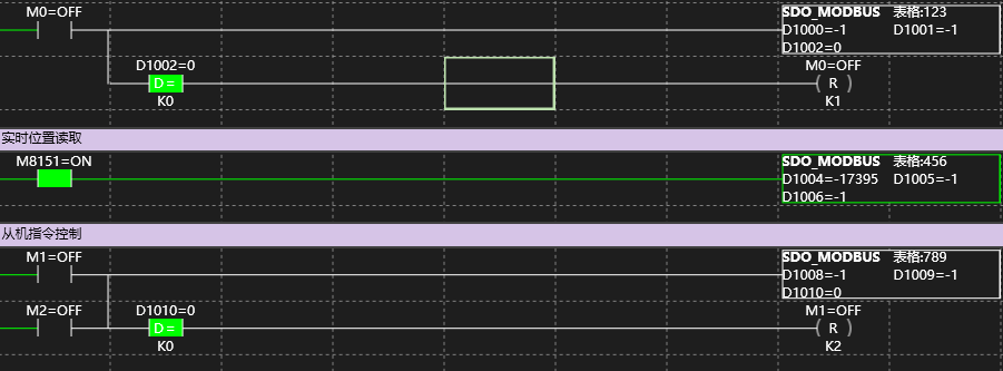
图10 SDO3.4
iii. Add the SDO-MODBUS instruction to the ladder program, select the corresponding table, and fill in the indicating registers for the MODBUS index (16 bits) pending, the MODBUS index Errorid (16 bits), and the reabortID (32 bits) in sequence. The first and two empty values are 0xFFFF. When calling for this instruction, it will indicate the current sending situation, and the return code empty value is 0xFFFFFF. After successfully completing the sending and receiving of all tables corresponding to this instruction, it will return 0 (keep 10ms) until the next calling for this instruction or returning other error codes (check 3-f: SDO-READ/WRITE instruction).
f) During the running of the ladder program, the data in all enabled tables will be read and written one by one.To prevent excessive canbus load, there will be a certain interval between the read and write of each register, and the read and write speed is proportional to the baud rate. At speed of 1Mbps, the read and write time of a single register is about 0.2ms, with an interval of 10ms. Users can also use the ladder program to control the transmission frequency to reduce canbus load.
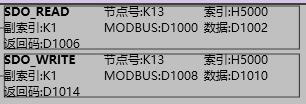
图11 SDO3.5
Both the CPU and expansion module can be Set the single word "node ID", the single word "index" to H5000, the single word "sub index" to K1, and the single word "Modbus index" to refer Modbus address shift table setting, reading data storage of starting register adress or writing data as a original "data", occupying a length of 4 single word registers (the maximum length of CAN communication data is 8 bytes, and Samkoon register H5000 only uses 2 bytes). sending and displaying transmission status is a double word address "return code".
Write 1 to the “return code” to trigger a transmission request, and the return code will display the transmission status (when using Samkoon protocol for transmission, users only need to pay attention to the bold words):
0x0000000, transmission completed; 0x00000001, in transmission; 0x00000002, SDO busy;
0x05040000, transmission timeout; 0x05040001, command line exception; 0x06010000, object inaccessible;
0x06010001, object unreadable; 0x06010002, object is not writable; 0x06020000, object does not exist;
0x06060000, hardware error; 0x06070010, length mismatch; 0x06070012, length too long;
0x06070013, length too short; 0x06090011, sub index does not exist; 0x06090030, the value exceeds the limit;
0x06090031, the value is extremely high; 0x06090032, value too low; 0x06090036, abnormal upper and lower limits;
0x060A0023, SDO source abnormality; 0x080000000, general error; 0x08000020, application layer error;
0x08000021, under local control; 0x08000022, abnormal device status; 0xFFFFFFFE, CANopen not initialized.
In addition, these two instructions also support SDO read and write with other CANOpen devices. At this time, the modbus index is used as a parameter for reading data length (in Bytes, up to 8). For related functional applications, please consult Samkoon technical support.
g) Some models of the S series PLC (S-8X8T, S-8X8T-C, S-16T, S-16T-C) can also be used as CPU. When configuring models, choose the model branch with “M”, and the rest configuration methods are the same as in 2-d, but note that there can only one CPU in a CAN network.
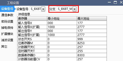
图12 SDO3.6
1.4. Joint debugging
a) S series PLC and related models are using the general protocol CANOpen, which supports connection with other CANOpen devices. SDO instructions can be used directly, and the PDO configuration is not open and requires adaptation of the underlying software. Relevant requirements can be consulted with Samkoon technical support.
b) In addition to the CANopen protocol, we also provide basic CAN protocol for communication instructions REV-CAN/SEND-CAN. Data frames are transmitted using the “Iden mask” mode, and extension module tab needs to be selected to activate the CAN function.
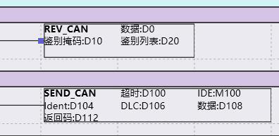
图13 SDO4.1
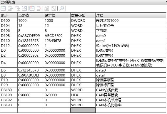
图14 SDO4.2
i. Receive instruction REV-CAN, setting the receive start register adress, Iden mask, and iden list, enable instruction to continuously input the filtered data from the CAN bus into the five doubleword addresses, which are {uint32t StdId, uint32ut ExtId, uint8t IDE, uint8t RTR, uint8t DLC, uint8t FMI, and uint8_t Data [8]}
Ii. Sending instruction SENd_CAN, it is necessary to set the Timeout, IDE, identifier, data length DLC, data content register, and return code register ,enable the command, the return code value= 1 will start sending once, and the return code will be automatically written to 0 when success. Otherwise, an error code will be returned:
0x00000001, in transmission; 0x00000003, IDE error; 0x00000004, length error; 0x05040000, Time out.
Iii. This instruction is only allowed to appear once globally in the ladder program, and users can send and receive different data by modifying parameters and return codes.