1. Free port receiving REV
1. Free port receiving REV
1.1. Command description
COM-ID (communication port selection): COM0 (485) or COM1 (485) can be selected;
Addr (starting address): Stores the received data in an area starting from Dn, and this operand can only select the D data register;
Len (receiving length): This parameter does not need to be set and will automatically return the actual received data length during the data receiving process, which will be stored in the set D register. Different models of PLCs have their corresponding maximum receiving limits;
Modify configuration information: Select [COM port communication parameter settings] (ComConfig. html), such as baud rate, parity, etc., and select the free port communication mode, as well as the number of data buffer bits;
1.1.1. Explanation of communication data buffer bits:
8-bit: The high 8-bit bytes of the D register are invalid during communication, and the PLC only uses the low 8-bit bytes of the D register for sending and receiving;
16 bits: During communication, the PLC first stores the received data in the lower 8 bits of the D register, and then stores it in the upper 8 bits of the D register;
It should be noted that regardless of whether 8-bit or 16 bit data buffer bits are selected, the received length Len returned during communication is byte length. When 8-bit is selected, a D register is one byte length, while when 16 bit is selected, a D register is two bytes length;
In addition, every time before receiving data and after re enabling the REV instruction, the buffer data stored in the D register will be automatically cleared. Therefore, the REV instruction is often used in conjunction with the MVBLK instruction;
1.1.2. COMn is receiving flag bits(Only Read):
| register | port COMn |
|---|---|
| M8178 | COM0(485) |
| M8179 | COM1(485) |
1.1.3. COMn Received completion flag(Read or Write)
| register | port COMn |
|---|---|
| M8182 | COM0(485) |
| M8183 | COM1(485) |
Attention:**
To use this command, the set COM port (485) must be set to free port communication mode. Please refer to the PLC parameter settings page for specific settings;
When the COM port mode is set to free port communication, the COM port cannot be used for program download and monitoring, nor can it be used as a Modbus master or slave;
After modifying the PLC parameter settings, it is necessary to check the configuration information and download it to the PLC, otherwise the parameter modification is invalid;
Due to the limitation of PLC data cache size, the received data length Len cannot exceed its maximum limit, which is 260 bytes;
Free port communication transmission belongs to half duplex mode, which means that sending command SEND and receiving command REV cannot be performed simultaneously;
1.2. The valid operands of the instruction
| Input/Output | Data Type | operand | Description |
|---|---|---|---|
| COM | 16 bit integer | K/H | Communication port |
| ADDR | 16 bit integer | D | Address |
| LEN | 16 bit integer | D/CV/TV/AO/V/Z, bit composite word (Y/M/C/T/S), local variable (LW) | length |
1.3. Example 1
command table:
NETWORK 000
LDP M000
REV K1 D0 K1000 //Select COM1 (485) and set the starting address to D0. When the REV instruction is enabled, data from COM1 (485) will be received;
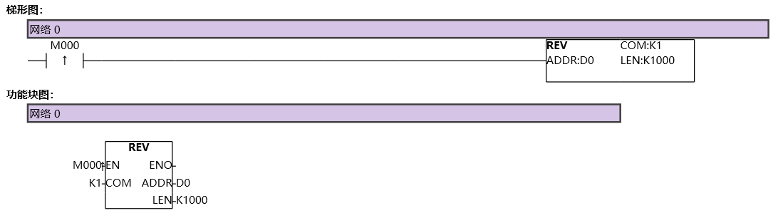
图1 REV1
Assuming receiving 0x10 0x11 0x12 0x13 0x14;
If the data buffer bit is 8, the received length Len returned is 5, D0=16,D1=17,D3=18,D4=19,D5=20;
If the data buffer bit is 16, the received length Len returned is 5, D0=4368,D1=4882,D2=20;
1.4. Example 2
command table:
NETWORK 000
LD M0
REV K0 D1 D0 // After configuring the relevant parameters of the COM0 port, enable the REV of COM0 to receive instructions, store the received data in an area starting from D1, and store the returned receiving length in D0;
NETWORK 001
LDP M8182 // M8182 is the reception completion flag bit of COM0. When data reception is completed, this bit will automatically set to 1. It needs to be manually reset in the program, otherwise it will remain at 1;
SEND K0 D1001 D1000 // When the COM0 port receives data once, it will enable the SEND command to send an area of length D1000 starting from D1001 to the COM0 port;
RST M8182 K1 // Clear the M8182 reception completion flag;
NETWORK 002
LDF M8178 // M8178 is the receiving flag bit of COM0 port. Whenever data reception is completed, a falling edge will be generated. This bit is read-only and is only controlled by the program. Setting/resetting it is invalid;
MVBLK D1 D2000 D0 // Store the received data in blocks in another area to facilitate other instruction operations on the received data;
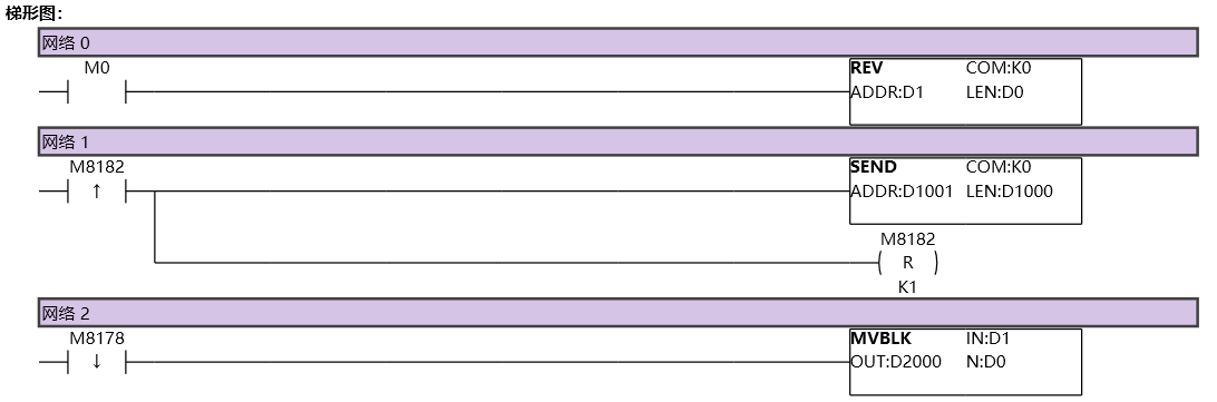
图2 REV2
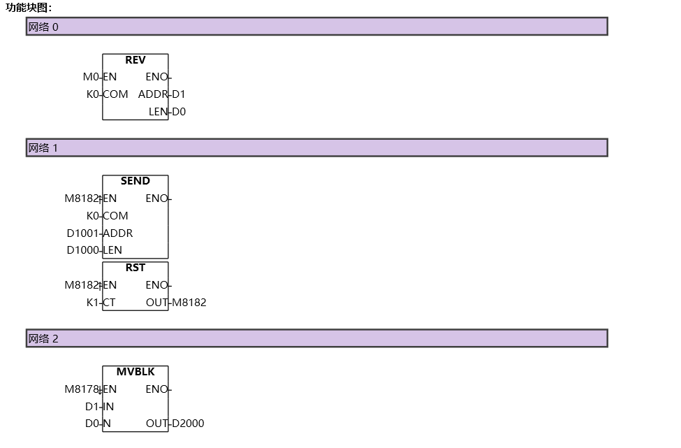
图3 REV3