1. Modbus master communication MBUS
1. Modbus master communication MBUS
1.1. command description
Communication port (COM-ID): Communication port selection, can choose COM0 (k0) or COM1 (K1);
Master Table: Modbus Master Table ID, which can be used to add the required Modbus Master Table in the project management window;
Information Code (WR): Used to store communication information codes (see table below);
Command Number (WR-ID): Used to store the Modbus command sequence number of the current master station table, indicating which command sequence is currently running to the table. The number ranges from 0 to n-1, where n is the total number of command sequences in the table;
Modify configuration information: Select [COM port communication parameter settings] (ComConfig. html), such as master station number, baud rate, checksum, timeout time, retransmission frequency, etc., and then select Modbus master station mode;
Attention::
To use this instruction, the set COM port (COM0/COM1) must be set to master station mode and the configuration information must be checked to download to the PLC, otherwise the communication command will not be executed;
For Modbus master, the timeout time for serial communication can be set to 200ms by default, and the number of retransmissions can also be set to 3 by default. For example, when the timeout time is set to 200ms and the number of retransmissions is 3, it means that if the slave station does not return within 200ms, the PLC will resend the data packet. If the cumulative number of retransmissions exceeds the set 3 times and the slave station still does not respond (at this time, the PLC has sent 4 data packets in total), a message timeout error code 16, which is 0x10, will be returned;
The timeout period may need to be slightly adjusted by the user based on the actual situation, such as when the baud rate is low and the data transmission speed is slow, the timeout period needs to be appropriately increased; In addition, if the number of bytes in each transmission packet is large (such as when the length of each read and write slave station is large, causing a longer time to send or receive the packet data), the timeout time also needs to be increased, otherwise a communication timeout error may be reported;
The communication information code returned by the PLC during operation is stored in the set Dn register, which is a decimal number. However, the values in the table below are all hexadecimal numbers. For example, if the communication return Dn value is 16, converted to hexadecimal=0x10, it indicates a communication timeout;
For the same COM port, it is impossible to communicate data with multiple slave stations at the same time. The internal access of PLC to external slave station devices is executed sequentially, and users should consider this when programming. If one of the slave station devices disconnects, it will cause the entire system to lag for a period of time due to multiple retransmissions at that slave station. The lag time is: (number of retransmissions+1) * timeout time. Therefore, if it is necessary to improve the fast response of the entire system, it can be considered to reduce the number of retransmissions;
Communication information code:
| Code | Information |
|---|---|
| 0x01 | Illegal Function Code |
| 0x02 | Illegal address |
| 0x03 | Illegal data |
| 0x04 | Slave operation failed |
| 0x05 | The command is valid and is currently being processed |
| 0x06 | Slave busy |
| 0x07 | Illegal data type |
| 0x08 | Illegal command number |
| 0x09 | Illegal password |
| 0x10 | Communication timeout |
| 0x11 | Numerical error: Data less than 0 or greater than 255 |
| 0x12 | master-slave station setting error |
| 0x13 | The station number in the actual received data does not match the expected station number |
| 0x14 | Component Address Overflow: The amount of data sent exceeds the storage space of the component |
| 0x15 | Command execution failed |
| 0x18 | Received information frame error, including received length check error, received CRC check error |
| 0x20 | Parameter cannot be modified |
| 0x21 | Parameter cannot be modified during runtime |
| 0x22 | Parameter is password protected |
1.2. The valid operands of the instruction
| Input/Output | Data Type | operand | Description |
|---|---|---|---|
| COM | 16 bit integer | K/H | Communication port |
| TBL | Text | Table | |
| WR | 16 bit integer | D | Code |
| WR-ID | 16 bit integer | D | Number |
1.3. Basic usage method
Right click on the "Project" ->"Modbus Table" folder in the project management window, click on "New Modbus Table", and then a new dialog box will pop up.
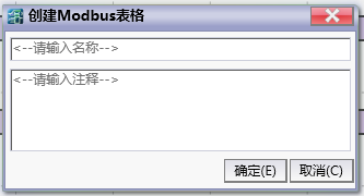
图1 New Modbus table
Enter the table name (here it is "Modbus Master Table"), and then click the OK button. You can add and edit this table now.
For specific details, please refer to How to Input a Modbus Table。
Instruction table:
NETWORK 000
LD X000
MBUS K0 Modbus Master table D0 D1 // K0 represent COM0,use“Modbus master table”,D0 stores communication information, and D1 stores the current Modbus command number being executed
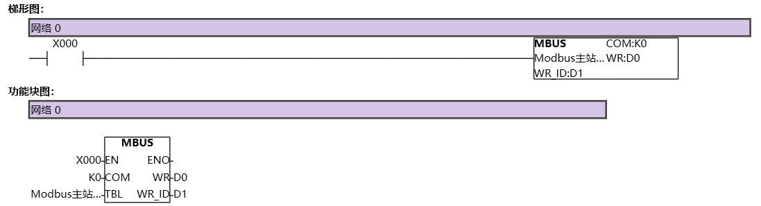
图2 MBUS1
PLC ladder diagram operation process:
First, execute the table command with station number 1. The PLC sends a data packet to the device with station number 1 and waits for the station to return information. At this point, D1=0;
During this period, even if the PLC scans the instruction, it will not execute the corresponding command until the slave device in the first table command returns correctly or exceeds the timeout, and then the commands in the Modbus table will be executed;
After the first table command is executed, when the ladder diagram scans the instruction again, the second command of the table will be executed in sequence, that is, the PLC will send a data packet to the device with station number 5 and wait for the station to return information. At this time, D1=1;
The third table command is similar to the previous two, executed in a loop with D1=2;
It should be noted that for the same COM port, it is impossible to communicate with multiple slave devices simultaneously. There must be a sequence between them, but this sequence is executed quickly and can even be considered as synchronous execution;
1.4. Expand applications
The Modbus master communication instructions of PLC are very flexible in use and suitable for various situations and requirements,
1.4.1. (1) The master station must communicate with all slave stations simultaneously and continuously
This situation is the simplest for writing ladder diagram programs. All the address information of the slave stations to be read and written needs to be established in the same Modbus master table. In the entire ladder diagram program, there is only one Modbus master communication instruction for the COM port, and users can use a certain enable terminal to control it. Users do not need to handle the conversion between multiple slave stations, nor do they need to understand how to implement it, because the PLC will automatically switch it internally, and the switching will be automatically performed in the order of the slave station serial number WR-ID in the Modbus table;
The advantage of this method is that ladder diagram processing is simple, requiring only one Modbus instruction and creating a Modbus table, making it easier for users to write ladder diagram programs;
The disadvantage of this method is that when there are many mounted slave stations or a large number of slave station information sequences to be read or written, switching between each slave station information in a polling manner results in longer time consumption;
Therefore, this method is suitable for situations where the master station must always maintain communication with all slave stations, or where there are few commands from slave stations and read/write slave stations;
1.4.2. (2)The master station communicates with certain slave stations based on user selection, without communicating with other unselected slave stations
In some large-scale usage scenarios, it is more common for users to selectively communicate with certain slave stations, while unselected slave stations do not require read-write communication operations;
And this method can achieve any form of communication, including (1). A simple example will be given below to illustrate,
The advantage of this method is that it selectively communicates with certain mounted slave stations, resulting in faster communication speed compared to polling all slave stations in (1);
The disadvantage of this method is that the ladder diagram writing is relatively complex and requires the use of certain serial communication flags such as M8182/M8183 for users to manually control the switching of different Modbus tables and Modbus commands;
1.4.3. Example 1.
As shown in the table below, create a Modbus table named "All Slave Stations", where the master station mounts three slave stations with station numbers 1, 2, and 3. Each slave station has three different read and write sequences,
Table: All Slave Stations
| Slave station number | Function code | Slave station register | Slave station length |
|---|---|---|---|
| 1 | 0x03 (Read Double Word) | 60200 | 1 |
| 1 | 0x01 (read bit) | 30000 | 10 |
| 1 | 0x03 (Reading) | 40000 | 10 |
| 2 | 0x03 (Read Double Word) | 60200 | 1 |
| 2 | 0x01 (read bit) | 30000 | 10 |
| 2 | 0x03 (Reading) | 40000 | 10 |
| 3 | 0x03 (Read Double Word) | 60200 | 1 |
| 3 | 0x01 (read bit) | 30000 | 10 |
| 3 | 0x03 (Reading) | 40000 | 10 |
After creating the table, select the Modbus master communication protocol configuration, check the slave serial port information and station number settings, and download the master station ladder diagram as shown in the following figure to the PLC. Monitor and observe whether it is running normally, and the WR-ID is constantly switching quickly and automatically between the slave station sequence 0~8.
command table:
NETWORK 000
LD M6000
MBUS K1 to all slave D5000 D5001
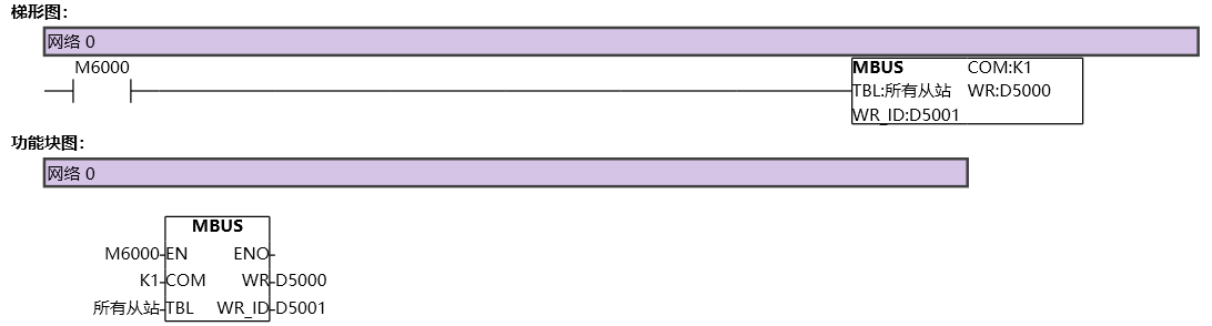
图3 MBUS2
1.4.4. Example 2.
Next, we will provide a method that can also implement Example 1. This method may be slightly more complex, but understanding its principles will lead to a deeper understanding of Modbus master communication instructions;
Firstly, separate the three slave stations in Example 1 into different Modbus tables, as shown in the following figure, and create three separate slave station tables;
Table:station 1
| Slave station number | Function code | Slave station register | Slave station length |
|---|---|---|---|
| 1 | 0x03 (Read Double Word) | 60200 | 1 |
| 1 | 0x01 (read bit) | 30000 | 10 |
| 1 | 0x03 (Reading) | 40000 | 10 |
Table:Station 2
| Slave station number | Function code | Slave station register | Slave station length |
|---|---|---|---|
| 2 | 0x03 (Read Double Word) | 60200 | 1 |
| 2 | 0x01 (read bit) | 30000 | 10 |
| 2 | 0x03 (Reading) | 40000 | 10 |
Table:Station 3
| Slave station number | Function code | Slave station register | Slave station length |
|---|---|---|---|
| 3 | 0x03 (Read Double Word) | 60200 | 1 |
| 3 | 0x01 (read bit) | 30000 | 10 |
| 3 | 0x03 (Reading) | 40000 | 10 |
Write a ladder diagram as shown below, where D1234 is used to switch and control different Modbus tables, enabling different Modbus instructions. For example, when (D1234==1), it represents controlling slave 1, and when (D1234==3), it represents controlling slave 3;
M8183 is the completion flag for 485 serial communication reception. This flag is automatically set by the PLC after receiving data and needs to be manually reset by the user in the ladder diagram. This special register is a key flag used for manual switching;
The meaning of comparing D5001, D5003, D5005, and K2 in the second network of the ladder diagram: K2 represents the slave information sequence of each Modbus table. In this example, since there are a total of three sequences in the three tables, and the sequence numbers in each table are 0, 1, and 2 respectively, comparing D5001, D5003, D5005, and K2 here indicates that the corresponding Modbus instructions run to the end of the sequence in the table. In practical engineering, the total number of sequence numbers in different tables can be different, but the end sequence number in each table must be the total number of sequences n \ -1 in that table, that is, the WRIDs are 0, 1, 2, etc N \ -2, n \ -1;
Downloading the program to the PLC allows for monitoring and debugging by setting M6000 and D1234 to 1. Afterwards, it can be observed that the PLC will automatically switch quickly between three Modbus commands, and the read-write communication with multiple slave stations is also normal.
Command table:
NETWORK 000
LDP M8183
MPS
AW= D1234 K1
AW= D5001 K2
MOV K2 D1234
MOV K0 D5003
MRD
AW= D1234 K2
AW= D5003 K2
MOV K3 D1234
MOV K0 D5005
MRD
AW= D1234 K3
AW= D5005 K2
MOV K1 D1234
MOV K0 D5001
MPP
RST M8183 K1
POP
LD M6000
MPS
AW= D1234 K1
MBUS K1 station 1 D5000 D5001
MRD
AW= D1234 K2
MBUS K1 station 2 D5002 D5003
MPP
AW= D1234 K3
MBUS K1 station 3 D5004 D5005
POP
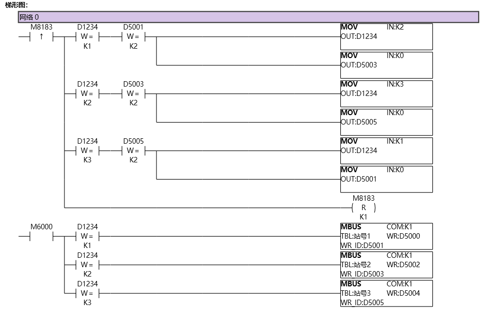
图4 MBUS3
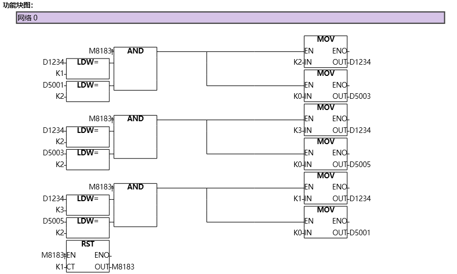
图5 MBUS4
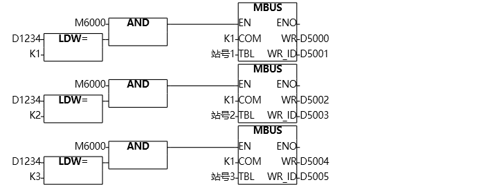
图6 MBUS5
If one can understand the program in Example 2, then it would be very simple and clear to achieve selective manual switching of control and communication with different slave stations;
Imagine a scenario where when the HMI enters screen 1, the user needs to communicate with slave 1 and not with any other slave, and when entering screen 2, the user needs to communicate with slave 2 and not with any other slave When entering screen n, it is necessary to communicate with slave station n and not with other slave stations; The different screens in this usage scenario are equivalent to D1234 in Example 2 above. Multiple different slave stations have multiple different Modbus tables and corresponding Modbus instructions. Example 2 implements automatic loop switching, while this usage scenario is manually switched by the user assigning different values to the D1234 register. The basic idea is the same, as long as the M8182/M8183 serial port reception completion flag is flexibly used and combined with the WR-ID in the Modbus instruction, any communication method can be achieved** Another key point to note is that the ladder diagram allows multiple Modbus commands to be included for the same COM port. However, within the same scanning cycle, only one Modbus command can be simultaneously conducted for the same COM port. If multiple Modbus commands are simultaneously conducted, data communication abnormalities may occur.