1. ModbusTCP Ethernet Master Station Communication Instruction MBUSTCP
1. ModbusTCP Ethernet Master Station Communication Instruction MBUSTCP
1.1. command description
This instruction serves as an Ethernet client for Ethernet MODBUS TCP communication with external Ethernet servers. Before using the MBUSTCP instruction, be sure to establish a connection between the motion controller and the external server using the DESTIP instruction. Please refer to the DESTIP instruction help document for details.
ID: Client ID, which can be set as K0~K5. This ID represents the connection number of the IP bound with DESIIP, that is, the remote IP selected to send data via Ethernet
Table: Modbus TCP master table ID, which can be added to the required Modbus master table in the project management window;
WR: Used to store communication information codes (see table below);
WR-ID: Used to store the Modbus command sequence number of the current master station table, indicating which command sequence is currently running to the table. The number ranges from 0 to n-1, where n is the total number of command sequences in the table
Modify configuration information: Enter PLC parameter settings, select the Communication Parameters tab, and then select the "Network Port" tab to set the communication parameters and network port parameters separately. In the communication parameters, select Modbus TCP/IP master mode;
Attention:
To use this command, you must select Modbus TCP/IP master mode and check the configuration information to download to the PLC, otherwise the communication command will not be executed;
The ID (client number) in the instruction parameter needs to be the same as the client number in the corresponding DESTIP instruction parameter;
The communication parameters can be set with a timeout period of 200ms by default, and the number of retransmissions can also be set to 3 by default. For example, when the timeout time is set to 200ms and the number of retransmissions is 3, it means that if the Ethernet server does not return within 200ms, the PLC will resend the data packet. If the accumulated number of retransmissions exceeds the set 3 times and the slave station still does not respond (at this time, the PLC has sent 4 data packets in total), a communication timeout error code 16, which is 0x10, will be returned;
The timeout period may need to be slightly adjusted by the user according to the actual situation at some times, such as when the number of bytes in each transmitted data packet is large (the length of each read and write slave station is large, causing a longer time to send or receive the packet data), the timeout period also needs to be increased, otherwise a communication timeout error may be reported;
The communication information code returned by the PLC during operation is stored in the set Dn register, which is a decimal number. However, the values in the table below are all hexadecimal numbers. For example, if the communication return Dn value is 16, converted to hexadecimal=0x10, it indicates a communication timeout;
The DESIIP instruction can bind up to 6 server IPs simultaneously, while the MBUSTCP instruction can connect multiple clients simultaneously. The same client ID but different client IDs are acceptable. The PLC will send data in the order of connection, but it is not possible to send multiple sets of data at the same time. Both the PLC and Ethernet servers execute sequentially, and users should consider this when programming. If one of the server connections is abnormal, it will cause the entire system to lag for a period of time due to multiple retransmissions at that connection. The lag time is: (number of retransmissions+1) * timeout time. Therefore, if you need to improve the fast response of the entire system, you can consider reducing the number of retransmissions;
The frame interval time is the shortest time between two adjacent Ethernet frames. During normal communication, if the frame interval time is too long, it will reduce communication efficiency. If it is too short, Ethernet communication will be too busy, which may cause communication abnormalities. It is recommended to set it to 2ms or more.
The table creation method and instruction usage are consistent with MBUS.
1.2. Communication Information Code
| Code | Information |
|---|---|
| 0x01 | Illegal Function Code |
| 0x02 | Illegal address |
| 0x03 | Illegal data |
| 0x04 | Slave operation failed |
| 0x05 | The command is valid and is currently being processed |
| 0x06 | Slave busy |
| 0x07 | Illegal data type |
| 0x08 | Illegal command number |
| 0x09 | Illegal password |
| 0x10 | Communication timeout |
| 0x11 | Numerical error: Data less than 0 or greater than 255 |
| 0x12 | master-slave station setting error |
| 0x13 | The station number in the actual received data does not match the expected station number |
| 0x14 | Component Address Overflow: The amount of data sent exceeds the storage space of the component |
| 0x15 | Command execution failed |
| 0x18 | Received information frame error, including received length check error, received CRC check error |
| 0x19 | TCP received message sequence number error |
| 0x20 | Parameter cannot be modified |
| 0x21 | Parameter cannot be modified during runtime |
| 0x22 | Parameter is password protected |
| 0x23 | TCP Not Connected Status |
| 0x24 | TCP Start Connection Status |
| 0x25 | TCP is currently connecting |
| 0x26 | TCP connection success status |
| 0x27 | TCP connection failure/timeout status |
1.3. The valid operands of the instruction
| Input/Output | Data Type | operand | Description | |
|---|---|---|---|---|
| ID | 16 bit integer | D/CV/TV/AI/AO/K/H/V/Z/FD, bit composite word (X/Y/M/C/T/S), local variable (LW) | client ID | |
| TBL | Text | Table | ||
| WR | 16 bit integer | D | Code | |
| WR-ID | 16 bit integer | D | Number |
1.4. Example
Connect M0, use DESTIP command to establish a connection with the remote server IP 192.168.1.200 port number 2000, and number the connection as K0. Use MBUSTCP command to send data to K0 connection, where the communication table uses mbus_socket0.
command table:
NETWORK 000
LD M0
MPS
MEP
MOV K192 D5000
MOV K168 D5001
MOV K1 D5002
MOV K200 D5003
MOV K2000 D5004
MPP
DESTIP D5000 K0 K65535 D5006
MBUSTCP K0 mbus_socket0 D5007 D5008
POP
LAD:
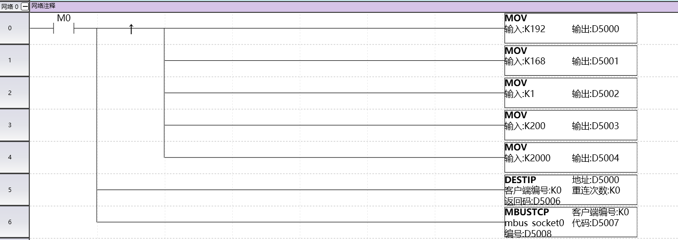
图1 MBUSTCP