1. Free port to send SEND
1. Free port to send SEND
1.1. Instruction Description
COM-ID (communication port selection): COM0 (485) or COM1 (485) can be selected;
Addr (starting address): This parameter address is an area starting from Dn, and this operand can only select the D data register;
Len (data length): Set the length of the data to be sent, which can be selected as K/H/D. Different models of PLCs have their corresponding maximum sending limits;
Modify configuration information: Select [COM port communication parameter settings] (ComConfig. html), such as baud rate, parity, etc., and select the free port communication mode, as well as the number of data buffer bits;
1.1.1. Explanation of Communication Data Buffer Bit:
8-bit: The high 8-bit bytes of the D register are invalid during communication, and the PLC only uses the low 8-bit bytes of the D register to send and receive data;
16 bits: During communication, the PLC first sends the low 8-bit byte data in the D register, and then sends the high 8-bit byte data;
It should be noted that regardless of whether 8-bit or 16 bit data buffer bits are selected, their transmission length Len is byte length. When 8-bit is selected, a D register is one byte length, while when 16 bit is selected, a D register is two bytes length;
1.1.2. COMn is sending flag bits(Only Read):
| Register | Serial port COMn |
|---|---|
| M8176 | COM0(485) |
| M8177 | COM1(485) |
1.1.3. COMn sends completion flag(Read or Write)
| Register | Serial port COMn |
|---|---|
| M8180 | COM0(485) |
| M8181 | COM1(485) |
Attention:
The prerequisite for using this instruction is to set the corresponding COM port (485) to free port communication mode. Please refer to the PLC parameter settings page for specific settings;
When a certain COM port mode is set to free port communication, the COM port can no longer be used for program download and data monitoring, nor can it be used for communication between Modbus master and slave stations;
In the absence of USB, it is recommended to use only the COM1 (485) port for communication, with COM0 (485) reserved for programming and data monitoring functions;
After modifying the PLC parameter settings, it is necessary to check the configuration information and download it to the PLC, otherwise the parameter modification is invalid;
Due to the limitation of PLC data cache size, the length of data sent, Len, cannot exceed its maximum limit of 260 bytes;
Free port communication transmission belongs to half duplex mode, which means that sending command SEND and receiving command REV cannot be performed simultaneously;
1.2. The valid operands of the instruction
| Input/Output | Data Type | operand | Description |
|---|---|---|---|
| COM | 16 bit integer | K/H | Communication port |
| ADDR | 16 bit integer | D | Address |
| LEN | 16 bit integer | D/CV/TV/AI/AO/K/H/V/Z/FD, bit composite word (X/Y/M/C/T/S), local variable (LW) | length |
1.3. Example 1
command table:
NETWORK 000
LDP M000
SEND K1 D0 K21 //Select COM1 (485), set the starting address to D0, and the length of the data to be sent to K21
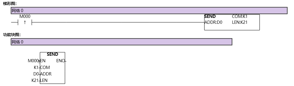
图1 SEND1
If the data buffer bit is 8, all the lower 8 bits of data in the D0-D20 registers, totaling 21 bytes, will be sent to COM1 (485);
If the data buffer bit is 16, a total of 21 bytes of data, including the high 8 bits, low 8 bits, and low 8 bits from registers D0-D10, as well as D11, will be sent to COM1 (485);
The enable terminal of the SEND instruction here is the rising edge, which means that it is sent once every rising edge. If the normally closed switch is selected to enable the SEND instruction, the data sending function will be executed every time the ladder diagram scans the instruction;
1.4. Example 2
Command table:
NETWORK 000
LD M0//First, configure the relevant parameters of the COM0 port in the parameter settings, and then check the configuration information to download to the PLC;
MPS
MVBLK D2000 D1 D0//The data block to be transmitted is sent to an area with a starting address of D1 and a length of D0 through the MVBLK instruction;
MPP
ANDN M8180//After completing data transmission, disable the SEND command and turn off data transmission from the COM0 port;
MEP
After enabling M0, send the data to the COM0 port;
POP
NETWORK 001
LD M8180//M8180 is the send completion flag for the COM port. When data transmission is completed, this bit will automatically set to 1 and needs to be manually reset in the program, otherwise it will remain at 1.
REV K0 D1001 D1000//After sending, REV will be enabled to accept instructions. The received data will be stored in an area starting from D1001, and the received length will be stored in D1000;
NETWORK 002
LDF M8178//M8178 is the receiving flag bit of COM0 port. Whenever data reception is completed, a falling edge will be generated. This bit is read-only and is only controlled by the program. Modifying this bit is invalid.
MOV D1000 D3000//When the data reception of COM0 port is completed, transfer the returned data reception length D1000 to D3000;
MVBLK D1001 D3001 D1000//Transfer the received data block with starting address D1001 to an area with starting address D3001, and the length of the transmitted data block is the length of the received data D1000;
RST M8180 K1//After data reception is completed, clear the M8180 send completion flag;
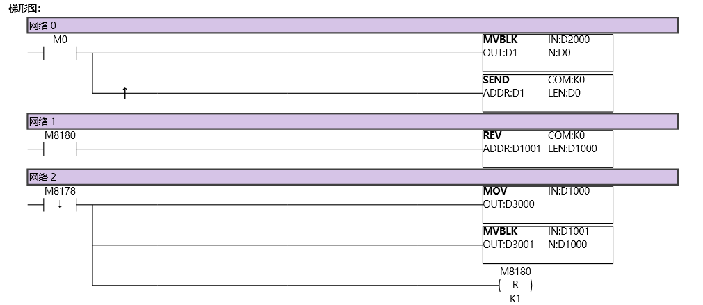
图2 SEND2
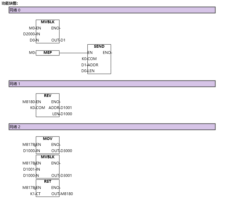
图3 SEND3