Absolute Value System Usage Instructions
Overview
The absolute value encoder not only detects the position of the motor within one rotation, but also counts the number of rotations of the motor. The single rotation resolution is 8388608 (23 bits)/131072 (17 bits), and it can store 16 bit multi rotation data. The use of absolute value encoders can be divided into absolute position linear mode and absolute position rotation mode, which can be used in position, speed, and torque control modes. When the driver is powered off, the encoder backs up the data through the battery, and after power on, the driver calculates the mechanical absolute position through the absolute position of the encoder, without the need for repeated mechanical origin reset operations.
User setting P00-03 (absolute position detection selection). When the battery is first connected, Al.045 (encoder battery fault) occurs, and an absolute encoder reset operation needs to be performed through F-004.
Note: When modifying C-002 (motor rotation direction definition) or performing absolute encoder reset (F-004), the absolute position of the encoder will undergo a sudden change, resulting in a change in the mechanical absolute position reference. Therefore, mechanical origin reset operation is required. When using the internal origin reset function of the drive, the mechanical absolute position and encoder absolute position deviation will be automatically calculated and stored in the drive EEPROM after the origin reset is completed.
5.5.2 Relevant function code settings
- Absolute value system settings
Code | Name | Set range | unit | value | Effective Mode | Set mode | Relevant Mode |
P00-03 | Absolute position detection selection | 0- Incremental Position Mode 1- Absolute position linear mode 2- Absolute Position Rotation Mode | - | 0 | power on again | Stop set | ALL |
Select absolute position mode through P00-03.
Note: In absolute position mode, the system automatically detects whether the motor mode is an absolute value encoder motor. If not, Al.039 (absolute position mode product matching fault) will occur.
- Encoder feedback data
The absolute value encoder provides feedback on the number of rotations and the position within one rotation,Incremental position mode no feedback number of rotations。
Code | Name | Set range | unit | value | Effective Mode | Set mode | Relevant Mode |
P13-34 | Encoder multi turn position | - | r | 0 | - | display | ALL |
P13-32 | Encoder single turn position | Encoder unit | 0 | - | display | ALL | |
P13-48 | Encoder position low 32 bits | Encoder unit | 0 | - | display | ALL | |
P13-50 | Encoder position high 32 bits | Encoder unit | 0 | - | display | ALL |
The absolute value encoder rotation data P13-34 is an unsigned number with a range of 0-65535, assuming the encoder resolution Rev:
The range of position P13-32 within one circle of the absolute value encoder is 0~Rev.
The absolute position of the absolute value encoder P13-50 * 232+P13-48 is calculated based on the feedback data P13-34, P13-32, and Rev .
When P13-34<32768, P13-50* 232 + P13-48 = P13-34 * Rev + P13-32
When P13-34 ≥ 32768, P13-50 * 232+P13-48=(P13-34-65536) * Rev+P13-32
- Absolute value position linear mode
Code | Name | Set range | unit | value | Effective Mode | Set mode | Relevant Mode |
P05-56 | Absolute position linear mode position offset (low 32 bits) | -2147483648~ 2147483647 | unit | 0 | Effective immediately | Stop set | ALL |
P05-58 | Absolute position linear mode position offset (high 32 bits) | -2147483648~ 2147483647 | unit | 0 | Effective immediately | Stop set | ALL |
P05-36 | Absolute position count value | unit | 0 | display | PST | ||
P13-38 | Mechanical absolute position (low 32 bits) | unit | 0 | - | display | ALL | |
P13-40 | Mechanical absolute position (high 32 bits) | unit | 0 | - | display | ALL |
In absolute value linear mode, the mechanical position can be recorded by absolute value encoder when power off. After the user performs the origin regression function, the driver will record the point as the mechanical origin ,and record the offset between original point of the encoder and mechanical original point.
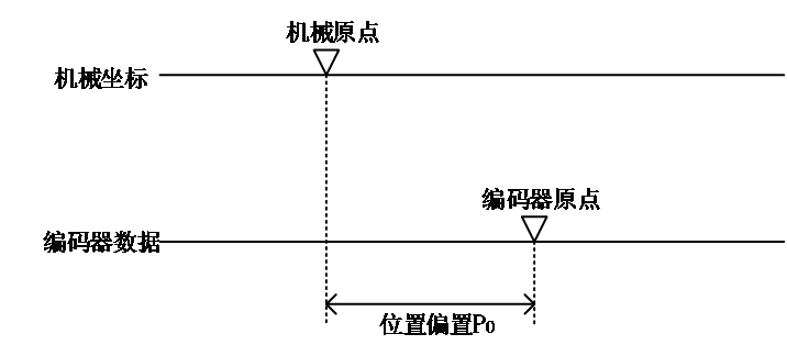
PM = PE – PO
Symbol | 说明 |
PM | Mechanical absolute position |
PE | Absolute position of encoder |
PO | Linear position offset |


In absolute value linear mode, the multi turns data range of encoder is -32768~32767. If the number of forward turns is more than 32767 or the number of reverse turns is less than -32768, AL.044 (encoder multi turn counter overflow) fault will occur. This fault can be canceled by setting P0B-17.
Code | Name | Set range | unit | value | Effective Mode | Set mode | Relevant Mode |
P0B-17 | Encoder multi turn overflow fault prohibited | 0- Allow faults 1- Shielding fault | - | 0 | Effective immediately | Stop set | ALL |
- Absolute value position rotation mode
The number of encoder pulses corresponding to one rotation can be set through P05-61/62 or P05-64/66, both of which can represent the number of encoder pulses corresponding to one rotation, with P05-64/66 having higher priority.
Assuming the encoder resolution RE,the number of encoder pulses corresponding to one rotation RM,when P05-64/66≠0, ,when P05-64/66=0,
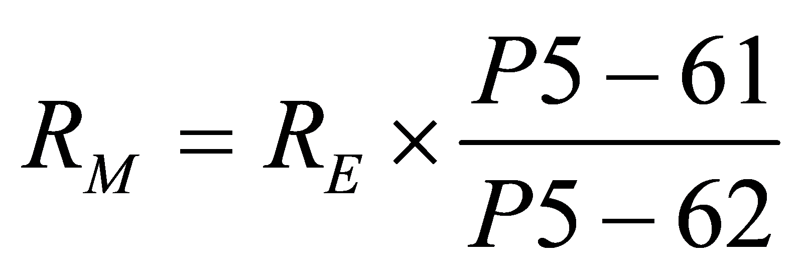
Code | Name | Set range | unit | value | Effective Mode | Set mode | Relevant Mode |
P05-61 | Multi turn absolute position mode 2 mechanical gear ratio molecule | 1~65535 | - | 1 | Power on again | Stop set | ALL |
P05-62 | Multi turn absolute position mode 2 mechanical gear ratio denominator | 1~65535 | - | 1 | Power on again | Stop set | ALL |
P05-64 | Multi turn absolute position mode 2 has a mechanical position upper limit value that is 32 bits lower | 0~4294967295 | -- | 0 | Power on again | Stop set | ALL |
P05-66 | Multi turn absolute position mode 2 has a mechanical position upper limit value that is 32 bits higher | 0~4294967295 | - | 0 | Power on again | Stop set | ALL |
The parameters related to location are defined in the following table
Code | Name | Set range | unit | value | Effective Mode | Set mode | Relevant Mode |
P13-38 | Mechanical absolute position (low 32 bits) | Encoder unit | 0 | - | display | ALL | |
P13-40 | Mechanical absolute position (high 32 bits) | Encoder unit | 0 | - | display | ALL | |
P13-44 | Rotating load single turn position (low 32 bits) | Encoder unit | 0 | - | display | ALL | |
P13-46 | Rotating load single turn position (high 32 bits) | Encoder unit | 0 | - | display | ALL | |
P13-42 | Rotating load single turn position | Command unit | 0 | - | display | ALL |
- The relationship between the load single turn position command unit (P13-42) and the encoder unit (P13-44/46) is:

Note that the electronic gear ratio here is the position loop electronic gear ratio (P05-02/P05-04), not the mechanical gear ratio.
- The relationship between the mechanical absolute position (P13-38/40) and the rotational load single turn position (P13-44/46) is:

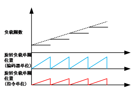
- The relationship between the number of load cycles and the position of a single load cycle is shown in the following figure. For every forward rotation of the load, the number of load cycles is increased by 1.
- Absolute encoder reset operation
The reset operation of the encoder through F-004
Code | Name | Set range | unit | value | Effective Mode | Set mode | Relevant Mode |
F-004 | Absolute encoder reset operation | 0- No operation 1- Absolute encoder alarm reset 2- Absolute encoder reset | - | 0 | Effective immediately | Stop set | ALL |