Origin reset function
Origin: refers to the mechanical origin, which can represent the position of the origin switch or motor Z signal.
The origin reset function refers to the position control mode, when the servo enable is ON, triggering the origin reset function, the servo motor will actively search for the zero point and complete the positioning function.
During the origin reset operation, other position commands (including the reset enable signal triggered again) are blocked. After the origin reset operation is completed, the servo drive can respond to other position commands.
The origin reset function includes two modes: origin reset and electrical zeroing.
Zero return at origin: After receiving the trigger signal for zero return at origin, the servo driver actively locates the relative position between the motor shaft and the mechanical origin based on the preset mechanical origin. First, it searches for the origin, and then moves the offset based on the origin to reach the zero position. Returning to zero at the origin is usually applied in the first attempt to find the zero point.
Electrical zeroing: After determining the absolute position of the zero point through the zero point zeroing operation, move a relative displacement from the current position as the starting point.
After the completion of the origin reset (including origin reset and electrical reset), the current absolute position of the motor (P13-36) is consistent with the mechanical origin offset (P05-48). After the origin return is completed, the servo driver outputs either the origin return completion signal or the electrical zeroing return completion signal. The origin return and electrical zeroing return completion signals are independent of the servo mode and servo operating status.
To use the origin reset function, a mechanical limit switch needs to be set in advance. If a limit signal is used for zeroing and a mechanical offset is used, please set the offset within the travel range to ensure that the origin reset process will not damage the machinery at high speed.
During the process of returning to the origin, if a limit switch is encountered, the servo drive will generate Al.114 (forward over travel warning) and Al.115 (reverse over travel warning). If P05-46=0 or 1, the servo motor will stop, and the stop mode will be determined by P0A-03 (over travel stop mode).
Table 5.1 Summary of Zero Return Methods
Zero return enable mode (P05-40) | Zeroing type | Trigger method | Zeroing method |
1-DI input enables zero return to origin | Origin rest | Servo enable+DI (32) trigger | Determined by P5-41 |
2-DI input enables electrical zeroing | Electrical zeroing | Servo enable+DI (32) trigger | Directly find the electrical zero point |
3- Perform origin regression after power on | Origin rest | Servo Enable | Determined by P5-41 |
4. Immediately return the origin to zero | Origin rest | Servo Enable | Determined by P5-41 |
5- Immediately perform electrical zeroing | Electrical zeroing | Servo Enable | Directly find the electrical zero point |
6- Using the current position as the origin | Origin rest | At any time | - |
Origin Return to Zero (Motion Return to Zero)
Using the following zeroing method as an example, explain how the origin returns to zero:
05-46=0 forward return to zero, deceleration point is the origin switch
05-46=1 reverse return to zero, deceleration point is the origin switch
05-46=2 forward return to zero, deceleration point is Z signal
05-46=3 reverse return to zero, deceleration point is Z signal
05-46=4 forward return to zero, deceleration point is the origin switch signal, origin is the Z signal
05-46=5 reverse return to zero, deceleration point is the origin switch signal, origin is the Z signal
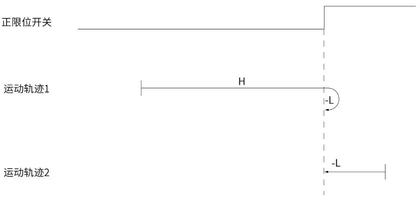
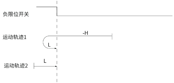
05-46=6 forward return to zero, deceleration point and origin are forward limit switches
05-46=7 reverse return to zero, deceleration point and origin are reverse limit switches
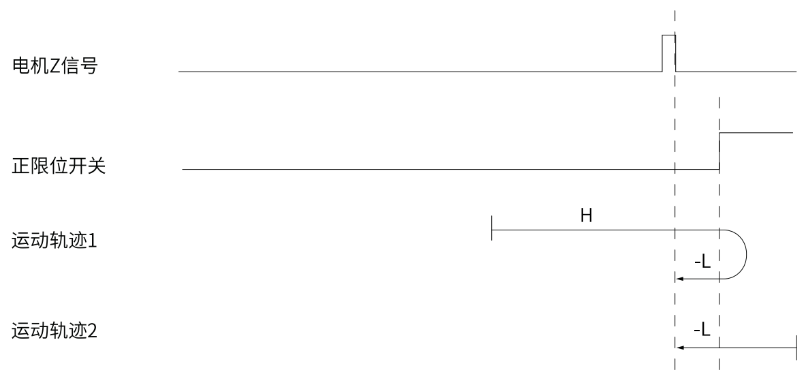
05-46=8 forward return to zero, deceleration point is forward limit switch, origin is Z signal
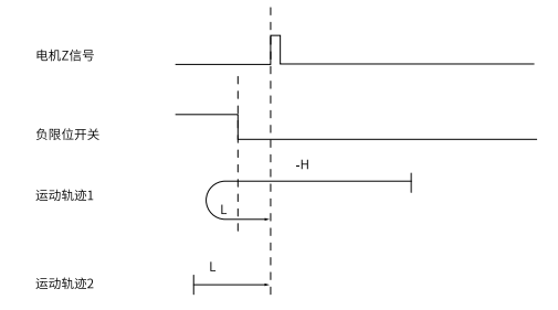
05-46=9 reverse return to zero, deceleration point is reverse limit switch, origin is Z signal
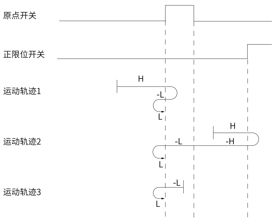
Below are the motion trajectories of each zeroing mode. In each figure, "H" represents the high-speed search of the origin of P05-42, and "L" represents the low-speed search of the origin of P05-43.
When there is a regression method for finding the origin switch, power on, when the motor is not in the origin switch position, the servo will search for the rising edge of the origin signal at high speed. After encountering the rising edge, it will start to find the falling/rising edge at low speed (different rules have different low-speed edges). The entire zeroing method is shown in the table below.。
Forward return to zero, deceleration point and origin switch (P05-41=0) | ■Movement trajectory 1: When the motor starts to move, the origin switch (deceleration point) signal is invalid, and the forward over travel switch is not triggered throughout the entire process. ■ Motion trajectory 2: When the motor starts to move, the origin switch (deceleration point) signal is invalid, and the forward over travel switch is triggered during the process. ■ Movement trajectory 3: When the motor starts moving, the origin switch (deceleration point) signal is valid, and the forward over travel switch is not triggered throughout the entire process. |
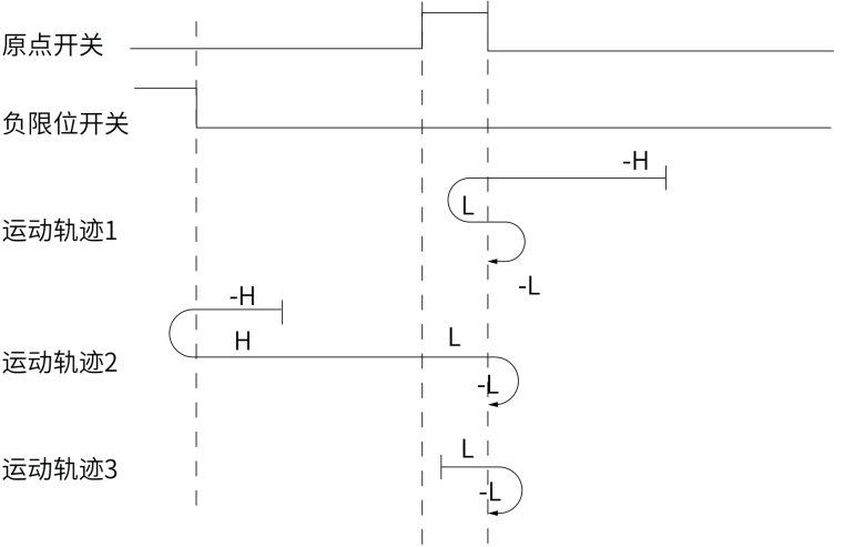
Reverse return to zero, with the deceleration point and origin as the origin switch (P05-41=1) | Movement trajectory 1,2and 3 When the motor starts moving, the signal from the origin switch (deceleration point) is invalid, and the reverse over travel switch is not triggered throughout the entire process. |
Forward return to zero, deceleration point and origin are motor Z signals (P05-41=2) | ■ Movement trajectory 1: The Z signal is invalid when the motor starts moving, and the forward over travel switch is not triggered throughout the entire process. |
Reverse return to zero, deceleration point and origin are motor Z signals (P05-41=3) | ■ Movement trajectory 1: The Z signal is invalid when the motor starts moving, and the reverse over travel switch is not triggered throughout the entire process. |
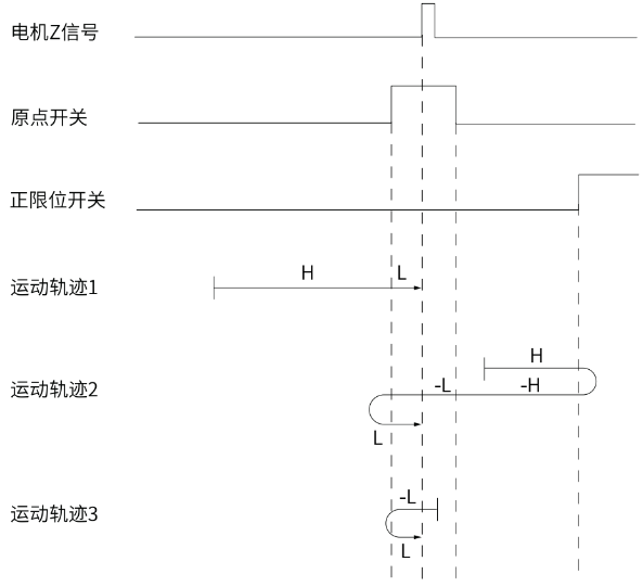
Forward return to zero, deceleration point is the origin switch, and the origin is the motor Z signal (P05-41=4) | ■ Movement trajectory 1: When the motor starts moving, the origin switch signal is invalid, and the forward over travel switch is not triggered throughout the entire process. ■ Motion trajectory 2: When the motor starts moving, the origin switch signal is invalid, and the forward over travel switch is triggered during the process. ■ Motion trajectory 3: When the motor starts moving, the origin switch signal is valid, and the forward over travel switch is not triggered throughout the entire process.。 |
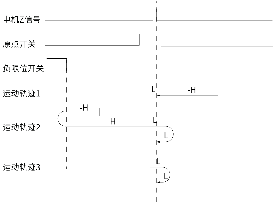
Reverse return to zero, with the deceleration point at the origin switch and the origin at the motor Z signal(P05-41=5) | ■ Movement trajectory 1: When the motor starts moving, the origin switch signal is invalid, and the reverse overtravel switch is not triggered throughout the entire process. ■ Motion trajectory 2: The origin switch signal is invalid when the motor starts moving, and the reverse over travel switch is triggered during the process. ■ Motion trajectory 3: When the motor starts moving, the origin switch signal is valid, and the reverse over travel switch is not triggered throughout the entire process. |
Forward return to zero, deceleration point and origin are forward overtravel switches (P05-41=6) | ■ Movement trajectory 1: The forward over travel switch signal is invalid when the motor starts moving. ■ Motion trajectory 2: The forward over travel switch signal is valid when the motor starts moving. |
Reverse return to zero, deceleration point and origin are reverse overtravel switches (P05-41=7) | ■ Movement trajectory 1: The reverse over travel switch signal is invalid when the motor starts to move. ■ Motion trajectory 2: The reverse over travel switch signal is valid when the motor starts moving. |
Forward return to zero, deceleration point is forward overtravel switch, origin is motor Z signal (P05-41=8) | ■ Movement trajectory 1: The forward over travel switch signal is invalid when the motor starts moving. ■ Motion trajectory 2: The forward over travel switch signal is valid when the motor starts moving. |
Forward return to zero, deceleration point is forward overtravel switch, origin is motor Z signal (P05-41=8) | ■ Movement trajectory 1: The reverse over travel switch signal is invalid when the motor starts to move. ■ Motion trajectory 2: The reverse over travel switch signal is valid when the motor starts moving. |


Using the current position as the origin
During on-site use, there is often a need to set the servo zero position. There are three ways to set the servo zero position:
Zero return enable mode (P05-40) | conditions for execution | description |
1-DI input enables zero return to origin |
| Both column 1 (P05-40) and column 2 (execution condition) must be met in order to set the current position as the origin。 |
2-DI input enables electrical zeroing |
| |
6- Using the current position as the origin | anytime |
Special attention: When using communication to write 6 to P5-40 to perform the "use current position as origin" function, the servo will automatically write P5-40 to 0 after the origin regression is completed. Please be careful not to keep writing 6 to P5-40, otherwise the servo will remain in the set origin state.
Origin and Zero Point
The relationship between origin and zero is mainly related to P5-48 (origin offset) and P5-46 (origin offset method).
When the P5-48 offset is set to 0, the zero point coincides with the origin. After the origin regression is completed, the current position is the origin, and the current position is also the zero point.
When P5-48 (offset) is not set to 0, after returning to the original position, the relationship between the origin and zero points is determined based on the P5-46 offset method. When P5-46 is set to 0 or 2, it stops once the origin is found and the current position is set to the value of P5-48 (offset); When P5-46 is 1 or 3, find the origin and then move P5-48 (offset).
P5-48 offset | P5-46 offset method | Operation effect | Origin and Zero Point Relationship |
= 0 | - | Stop after finding the origin and reset the current position to zero | The origin and zero point coincide |
= 0 | - | Stop after finding the origin and reset the current position to zero | |
≠ 0 | 0/2 | Stop after finding the origin and set the current position to the value of P05-48 | The origin and zero point not coincide |
≠ 0 | 1/3 | After finding the origin, reset the current position to zero, and then move the offset of P05-48 | The origin and zero point coincide |
Examples of Use
Implement a case where the origin can be set while running a certain distance and then returning to the set origin:
1) Set P05-40 to 2 and set the zeroing mode to electrical zeroing mode
2) Move the servo to the target origin position and input a trigger signal to the DI configured as number 30 to set the current position as the origin
3) The motor performs normal machining processes
4) When it is necessary to move the motor to the origin position set in "Step 2", input a current signal to the DI configured as number 32, and the motor can be moved to the origin position set in "Step 2" in the method of electrical zeroing.
Code related to origin reset
Code | Name | Set range | Unit | value | Effective method | Set method | Set mode |
|---|---|---|---|---|---|---|---|
P05-40 | Origin reset enable | 0-Close Origin Reset 1-Enable the origin reset function through DI input ORGSET signal 2-Enable electrical zeroing function by inputting ORGSET signal through DI 3-Immediately start the origin reset after power on 4-Immediately reset the origin point 5-Immediately electrical zeroing 6-Using the current position as the origin | -- | 0 | Effective immediately | Set anytime | Ordinary user |
P05-41 | Origin reset mode | 0-Forward return to zero, deceleration point is the origin switch 1. Reverse to zero, deceleration point is the origin switch 2- Forward return to zero, deceleration point is Z signal 3- Reverse to zero, deceleration point is Z signal 4- Forward return to zero, deceleration point is the origin switch signal, origin is the Z signal 5- Reverse to zero, deceleration point is the origin switch signal, origin is the Z signal 6-Forward return to zero, deceleration point and origin are forward limit switches 7-Reverse return to zero, deceleration point and origin are reverse limit switches 8-Forward return to zero, deceleration point is forward limit switch, origin is Z signal 9-Reverse return to zero, deceleration point is reverse limit switch, origin is Z signal 10. The current position can be set as the origin through DI triggering (32) | -- | 0 | Effective immediately | Set anytime | Ordinary user |
P05-42 | Origin high-speed search speed | 0~3000 | rpm | 100 | Effective immediately | Set anytime | Ordinary user |
P05-43 | Origin low-speed search speed | 0~1000 | rpm | 10 | Effective immediately | Set anytime | Ordinary user |
P05-44 | Origin acceleration and deceleration time | 0~1000 | ms | 1000 | Effective immediately | Set anytime | Ordinary user |
P05-45 | Origin search time | 0~65535 | ms | 50000 | Effective immediately | Set anytime | Ordinary user |
P05-46 | Origin offset and limit handling methods | 0~3(according to bit) bit0-origin offset or not bit1-reverse change when encountering a limit position or not | 0 | 0 | Effective immediately | Set anytime | Ordinary user |
P05-48 | Origin mechanical offset | -1073741824~1073741824 | ins | 0 | Effective immediately | Set anytime | Ordinary user |