Speed mode description
The speed control mode is divided into internal speed mode and analog input mode according to different command sources. Its usage steps are as follows:
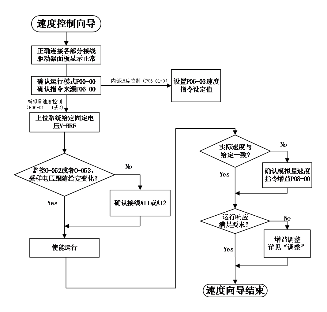
Figrue 5-4 Speed mode usage process
Speed mode wiring:
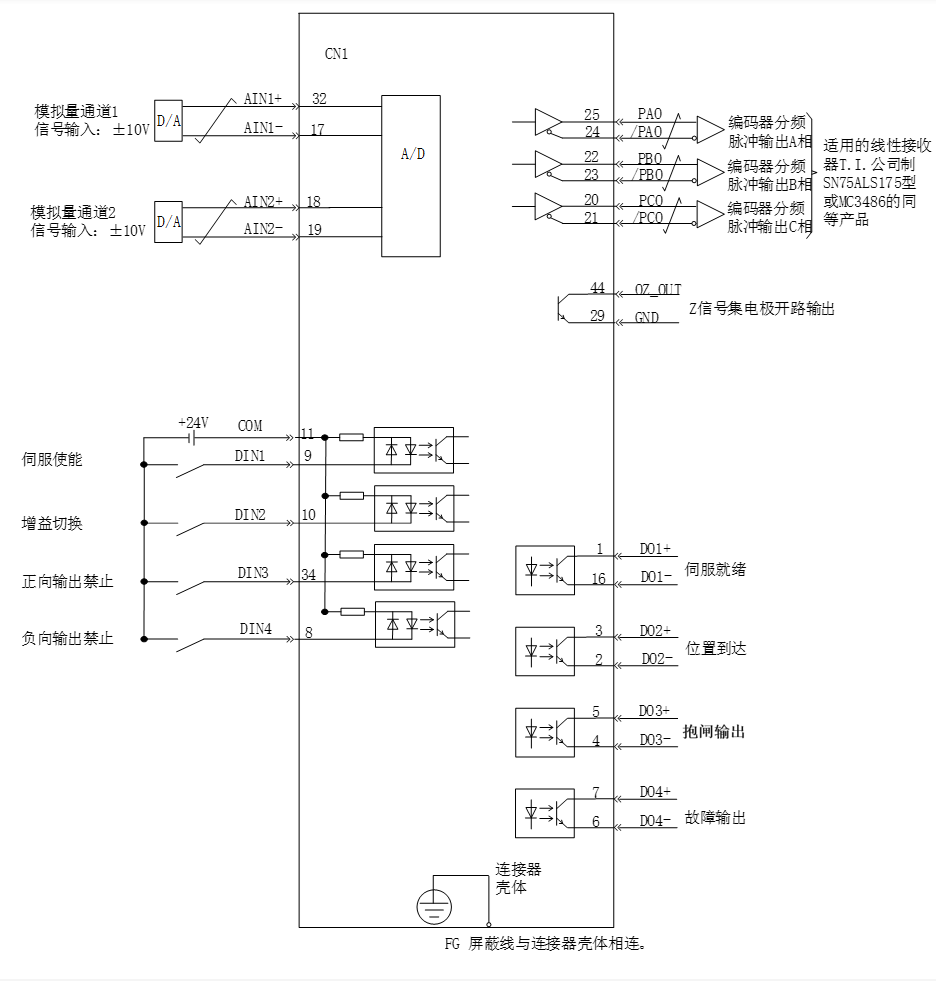
Figure 5-5 Speed mode wiring
 means twisted pair cables
Note :
- Signal cables and power cables must be wired separately, with a minimum distance of 30cm between them;
- When connecting signal cables due to insufficient length, the shielding layer must be reliably connected and grounded;
- +5V is referenced to GND, and+24V is referenced to COM -. Do not exceed the maximum allowable current, otherwise the driver will not function properly
speed mode related function codes
- Speed command input set
- speed command source
In speed control mode, there are two sources for speed commands: source A and source B
Code | Name | Set range | unit | value | Effective Mode | Set mode | Relevant Mode |
P06-00 | Speed command selection | 0 -command A 1 -command B 2 -command A and command B both 3 –command A or command B switch | - | 0 | Effective immediately | Stop set | S |
P06-01 | Source of Speed Instruction A | 0 – user data give by P06-03 1 – AI1 2 – AI2 | - | 0 | Effective immediately | Stop set | S |
P06-02 | Source of Speed Command B | 0 – user data give by P06-03 1 – AI1 2 – AI2 | - | 0 | Effective immediately | Stop set | S |
P06-03 | Speed command digital setting value | -6000~6000 | rpm | 200 | Effective immediately | Stop set | S |
P06-04 | Jogging speed setting value | 0~6000 | rpm | 1000 | Effective immediately | Stop set | S |
Among them:
- Keyboard setting, refers to storing speed value through function code P06-03 and using it as a speed command.
- Simulated speed command source refers to AI input signals into for controlling motor speed. Using AI1 as an example to illustrate the method of setting speed commands.
Table 4-4 Analog Set Speed Command
step | Operation method | Note |
1 | Set command source as AI1 input P06-00 = 0 P06-01 = 1 | Set the speed command source in speed control mode |
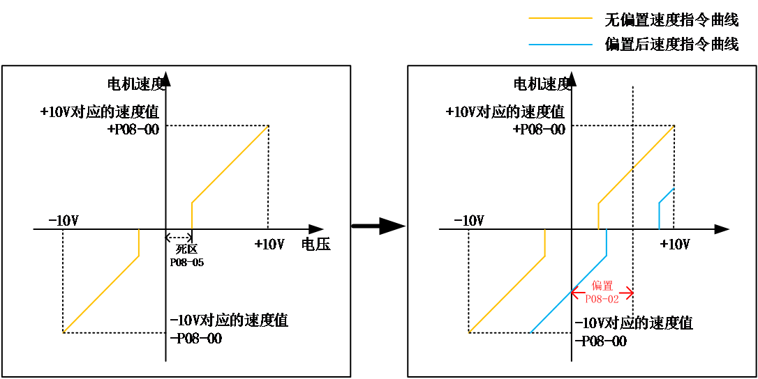
2 | Adjust AI1 related parameters:
| Adjust AI1 sampling through offset and dead zone settings |
3 | P08-00 Set the speed command value corresponding to 10V | Specify the maximum forward speed value corresponding to+10V Specify the maximum negative speed value corresponding to -10V |
When there is interference in the AI1 input signal, the AI1 low-pass filtering parameter P08-03 can be set for filtering processing.
The given speed command value can be viewed through O-003.
- Multi segment speed instructions refer to users selecting internal registers through external DI or internal specified methods, with 16 sets of speed instructions and related control parameters.
- Jogging speed command refers to the user configuring two external DI or upper computer control software to set the jogging operation function (FunIN.18, FunIN.19), using the speed value stored in function code P06-04 as the jogging operation speed, and selecting the direction of the speed command based on the DI status.
- Speed command direction switching
By setting the function code FunIN.26, DI can be used to control the direction switching of speed commands, meeting the needs of direction switching.。
Code | Function name | description | Note |
FunIN.26 | Speed command direction set | Invalid - positive direction valid - Reverse Direction | The recommended logic selection for the corresponding terminal is to set it as: current level valid |
- Speed command selection
The speed control mode has the following four ways to obtain speed commands, which are set through function code P06-00.
Code | Name | Set range | unit | value | Effective Mode | Set mode | Relevant Mode |
P06-00 | Speed command selection | 0 -command A 1 -command B 2 -command A and command B both 3 –command A or command B switch | - | 0 | Effective immediately | Stop set | S |
When the speed command selects "A/B switch",that is P06-00=3, a separate function definition needs to be assigned to the DI terminal. Through this input terminal, it is determined whether the current A or B command input is valid.
Code | Function name | description | Note |
FunIN.4 | Command switch | Invalid - The current running instruction is A Valid - The current running instruction is B | The recommended logic selection for the corresponding terminal is to set it as: current level valid |
- command ramp function setting
The ramp function control function refers to the process of converting rapidly changing speed commands into relatively smooth and constant acceleration and deceleration speed commands, and controlling acceleration and deceleration by setting acceleration and deceleration times. In speed control mode, if the given speed command changes too much, it will cause the motor to jump or vibrate violently. If the acceleration and deceleration time of soft start is increased, the motor can start and stop smoothly, avoiding the occurrence of the above situation and causing damage to mechanical components.
Code | Name | Set range | unit | value | Effective Mode | Set mode | Relevant Mode |
P06-05 | Speed command acceleration ramp time constant | 0 - 65535 | ms | 0 | Effective immediately | Stop set | S |
P06-06 | Speed command deceleration ramp time constant | 0 - 65535 | ms | 0 | Effective immediately | Stop set | S |
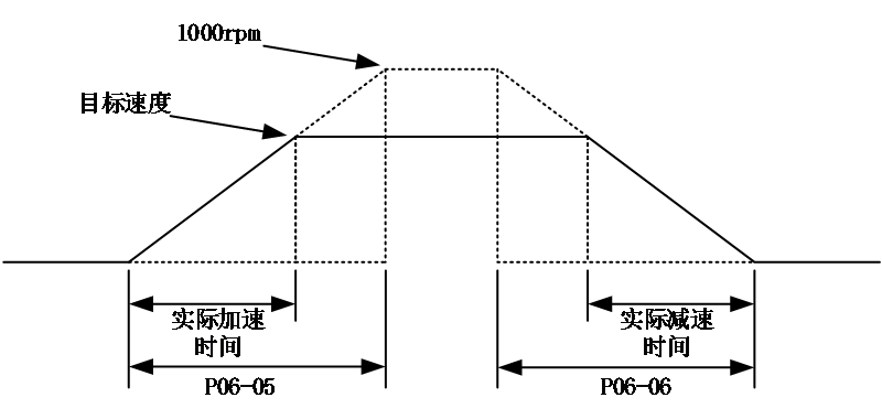
The ramp function control function converts step speed commands into smoother constant acceleration and deceleration speed commands, achieving smooth speed control (including internal set speed control).
P06-05:The time required for the speed command to accelerate from zero speed to 1000rpm.。
P06-06:he time required for the speed command to decelerate from 1000rpm to zero speed.。
The actual acceleration and deceleration time calculation formula is as follows:
Actual acceleration time=(speed command/1000) x speed command acceleration ramp time
Actual deceleration time=(speed command/1000) x speed command deceleration ramp time
- Speed command limit setting
In speed control mode, the servo drive can limit the value of the speed. Speed command limit as below:
- P06-07 sets the amplitude limit, and both forward and reverse speed will be limited within this value.。
- P06-08 sets the forward speed limit, and the forward speed will be limited within this value.
- P06-09 sets the reverse speed limit, and the reverse speed will be limited within this value.
- The maximum speed of the motor is the default limit point, and this parameter will change with the motor parameters when matching different motors.
Note :
When function codes P06-07, P06-08, and P06-09 limit the speed, the minimum limit point is used as the limiting condition, as shown in the following figure. The forward rotation speed is limited to P06-08, and because the set value of P06-09 is greater than P06-07, the reverse rotation speed is limited to P06-07.

Note: The maximum speed of the motor is the default maximum limit point.
The actual motor speed limit range meets:
|The amplitude of the forward speed command | ≤ min {maximum motor speed, P06-07, P06-08}
|The amplitude of the reverse speed command | ≤ min {maximum motor speed, P06-07, P06-09}
Code | Name | Set range | unit | value | Effective Mode | Set mode | Relevant Mode |
P06-07 | Maximum speed threshold | 0~6000 | rpm | 6000 | Effective immediately | Stop set | S |
P06-08 | Positive speed threshold | 0~6000 | rpm | 6000 | Effective immediately | Stop set | S |
P06-09 | Reverse speed threshold | 0~6000 | rpm | 6000 | Effective immediately | Stop set | S |
- zero position fixing function
In speed control mode, if ZCLAMP is valid and the amplitude of the speed command is less than or equal to the speed value set by P06-11, the servo motor enters the zero position fixed state control. If oscillation occurs at this time, the position loop gain can be adjusted. When the amplitude of the speed command is greater than the speed value set in P06-11, the servo motor exits the control of the zero position fixed state.
DI function selection:
Code | Function name | description | Note |
FunIN.12 | zero position fixing enable | valid-zero position fixing enable invalid-no zero position fixing | The recommended logic selection for the corresponding terminal is to set it as: current level valid |
Relevant code:
Code | Name | Set range | unit | value | Effective Mode | Set mode | Relevant Mode |
P06-11 | Zero position fixed speed command threshold | 0~6000 | rpm | 10 | Effective immediately | Stop set | S |