Instructions for Using Position Mode
According to the position instructions of the upper computer (such as pulse input) or the internal position instructions of the servo, the main steps for position control are as follows:
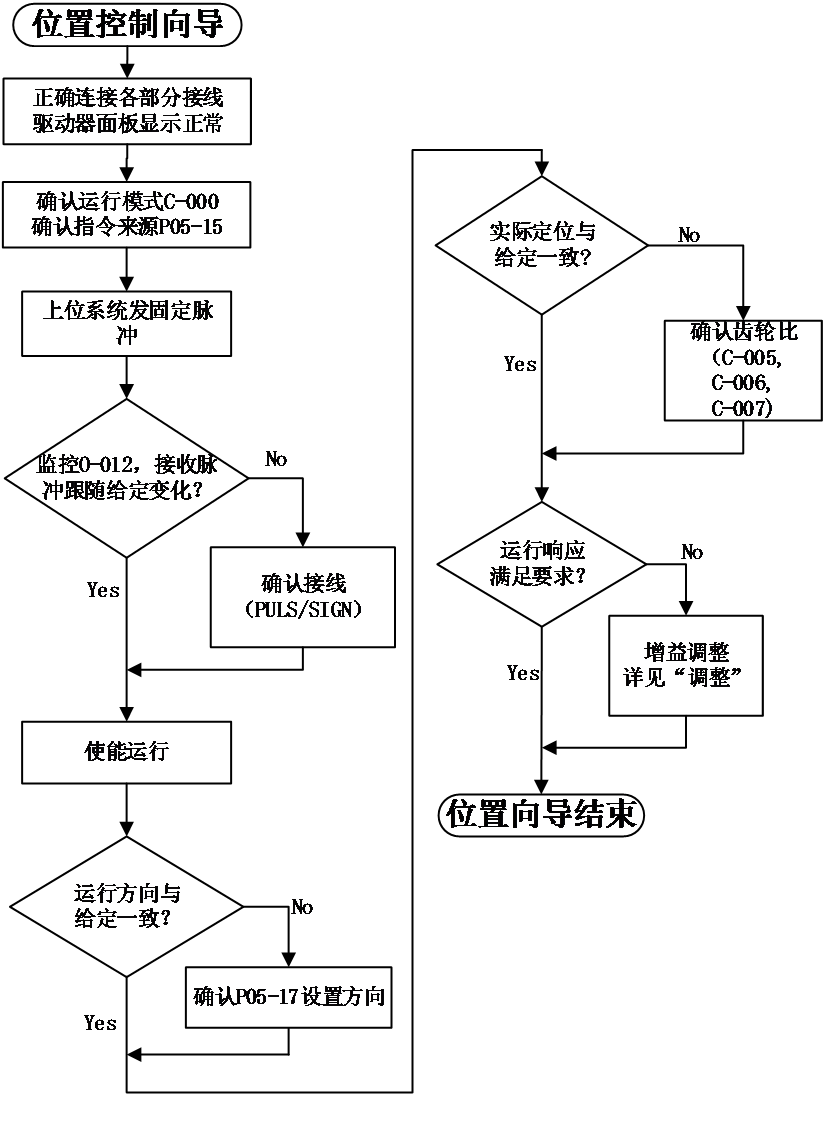
Figure 5-1 position mode set diagram
position mode wiring
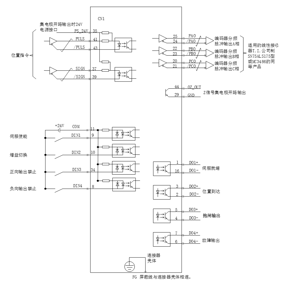
- Precautions:
- Signal cables and power cables must be wired separately, with a minimum distance of 30cm between them;
- When connecting signal cables due to insufficient length, the shielding layer must be reliably connected and grounded;
- +5V is referenced to GND, and+24V is referenced to COM -. Do not exceed the maximum allowable current, otherwise the driver will not function properly.
Function code settings related to position control mode
Parameter settings in position control mode, including mode selection, command pulse form, electronic gear ratio, DI/DO, etc.。
- Position command input settings
- Position instruction source
Set function code P05-15, specify position command source
Code | Name | Set range | unit | value | Effective Mode | Set mode | Relevant Mode |
P05-15 | Position instruction source | 0- Pulse input 1- High speed pulse input 2- Divided output OA and OB signals 3- Constant at 0 4- Internal multi-stage position input | - | 0 | Effective immediately | Stop set | P |
- Position command direction switching
By setting the DI function FunIN.27, it is possible to use DI to control the direction switching of position commands, meeting the needs of direction switching
Code | Function name | description | Note |
FunIN.27 | Position instruction direction | Invalid - positive direction Effective - Reverse Direction | The recommended logic selection for the corresponding terminal is to set it as: level valid |
- Pulse command form
Set function code P05-16 and select the form of external pulse command, including "direction+pulse", "orthogonal pulse", and "CW+CCW"。
Function code P05-17 can be set to reverse the instruction pulse signal. For example, in the "direction+pulse" mode, a value of 0 indicates positive logic, and a value of 3 indicates negative logic.
Code | Name | Set range | unit | value | Effective Mode | Set mode | Relevant Mode |
P05-16 | Command pulse form | 0-Pulse+direction 1- AB phase (4x frequency) 2 – CW + CCW 3- AB phase (1x) | - | 0 | Effective restart | Stop set | P |
P05-17 | Reverse the instruction pulse signal | 0- Pulse and Sign are not reversed 1- Pulse is reversed, Sign is not reversed 2- Pulse is not reversed, Sign is reversed 3- Pulse and Sign are both reversed | - | 0 | Effective restart | Stop set | P |
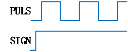
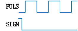
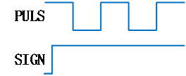
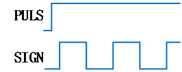
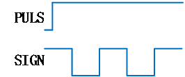
The principles of the three types of pulse command forms are shown in the table below
Pulse command form | Positive Logic | Negative Logic | ||
Forward | Reverse | Forward | Reverse | |
Direction+pulse |
|
|
|
|
Orthogonal pulse (A-phase+B-phase) |
|
| ||
CW+CCW |
|
| ||
|
| |||


- Selection of instruction pulse filter
Select the appropriate pulse filter based on the frequency of the highest pulse, which can be set through parameter P05-18. If choosing an inappropriate filter may result in the loss or increase of pulses received by the servo unit.
Code | Name | Set range | unit | value | Effective Mode | Set mode | Relevant Mode |
P05-18 | Pulse signal filtering time | 0~255 | - | 25 | Effective restart | Stop set | P |
- Pulse input prohibited
Disable pulse command input by setting DI function FunIN.13。
Code | Function name | description | Note |
FunIN.13 | Position instruction prohibited | Effective - Prohibit position command Invalid - Allow location command | set to level valid |
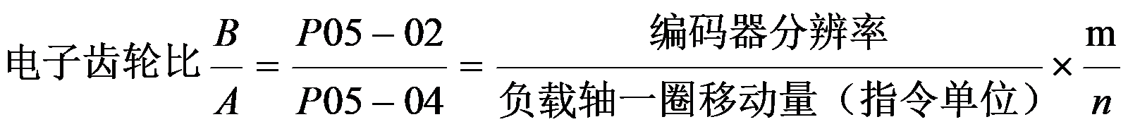
- Electronic gear ratio setting
Set the electronic gear ratio according to the actual situation.
Code | Name | Set range | unit | value | Effective Mode | Set mode | Relevant Mode |
P05-00 | Single cycle pulse count | 0~1048576 | - | 10000 | Effective restart | Stop set | P |
P05-02 | Electronic gear ratio 1 (molecular) | 1~1073741824 | - | 1 | Effective immediately | Running set | P |
P05-04 | Electronic gear ratio 1 (denominator) | 1~1073741824 | - | 1 | Effective immediately | Running set | P |
P05-06 | Electronic gear ratio 2 (molecular) | 1~1073741824 | - | 1 | Effective immediately | Running set | P |
P05-08 | Electronic gear ratio 2 (denominator) | 1~1073741824 | - | 1 | Effective immediately | Running set | P |
The principle of electronic gear ratio is shown in the following figure
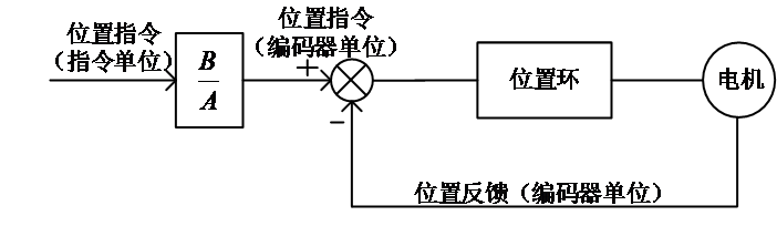
Figure 5-3 Principle diagram of electronic gear ratio action
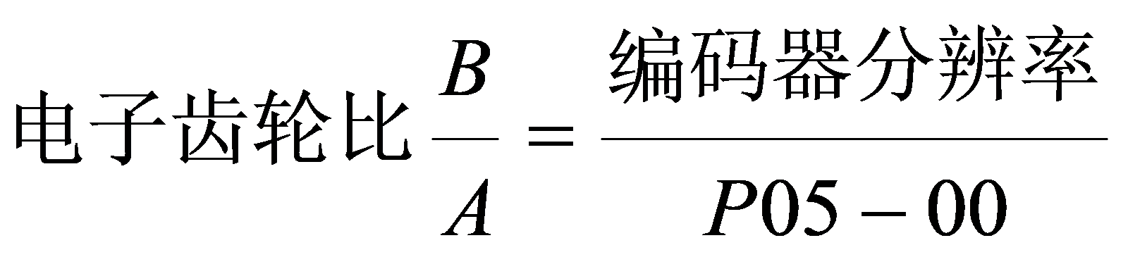
When P05-00=0::
The motor and load are connected through a reduction gear. Assuming that the reduction ratio between the motor shaft and mechanical load shaft is n/m (the electric shaft rotates m turns and the load shaft rotates n turns), the calculation formula for the electronic gear ratio is as follows:
The R8 servo supports up to 2 sets of electronic gear ratios and can use the gear ratio switching function (FunIN. 24) to complete gear ratio selection
When P05-00 ≠ 0:
At this time, the gear ratio is not related to P05-02, P05-04, P05-06, P05-08,and the gear ratio switching function is invalid.
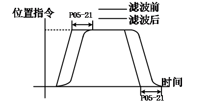
- Position instruction filtering setting
The position command smoothing function refers to filtering the input position command to make the rotation of the servo motor smoother. This function has a significant effect in the following situations
- The output pulse command of the controller device has not undergone acceleration/deceleration processing, and the acceleration/deceleration speed is very high;
- The instruction pulse frequency is too low;
- The electronic gear ratio is more than 10 times。
Note: This function has no effect on the displacement (total number of position commands).
The settings for the parameters related to the position command smoothing function are as follows
Code | Name | Set range | unit | value | Effective Mode | Set mode | Relevant Mode |
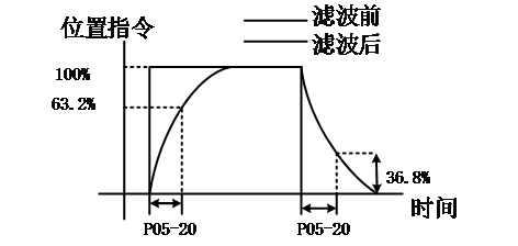
P05-20 | First order low-pass filtering time constant | 0.0~6553.5 | ms | 0.0 | Effective immediately | Stop set | P |
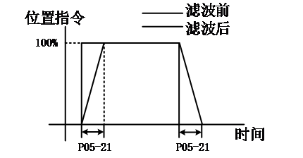
P05-21 | Mean filtering time constant | 0.0~128.0 | ms | 0.0 | Effective immediately | Stop set | P |
When the value is set to 0, the filter becomes invalid.
First order low-pass filtering time constant | Mean filtering time constant |
|
|
|
- Position deviation clearing function
By setting the DI function FunIN.35, DI can be used to control whether to reset the position deviation.
Code | Function name | description | Note |
FunIN.35 | Clear position deviation (Edge effective function) | Effective - Clearance of Position Deviation Invalid - Position deviation not reset to zero | The logical selection of corresponding terminals, Suggested setting: Edge valid。 |
- Frequency division output function
The servo pulse output source is selected by P05-25, and the pulse command synchronous output function is generally used in synchronous control situations
Code | Name | Set range | unit | value | Effective Mode | Set mode | Relevant Mode |
P05-25 | Selection of pulse input source | 0- Encoder frequency division output 1- Pulse command synchronous output 2- Prohibit output 3- Parameter triggered output | - | 0 | Twice power on | Stop set | ALL |
By setting P05-32, the pulse output signal type can be selected.
Code | Name | Set range | unit | value | Effective Mode | Set mode | Relevant Mode |
P05-32 | Pulse output signal type |
1- Pulse+ Direction 2 – CW+CCW 3 -AB phase, 1xfrequency | - | 0 | Effective immediately | Running set | ALL |
By setting P05-30, the servo driver will divide the frequency according to the set value and output it through the frequency division output port . The P05-30 set value corresponds to the number of pulse outputs。
Code | Name | Set range | unit | value | Effective Mode | Set mode | Relevant Mode |
P05-30 | Pulse output Number of single-phase pulses | 0~2147483647 | P/r | 2500 | Power on again | Stop set | ALL |
For example, when the pulse output signal type is selected as 0 (AB phase, 4x frequency), the motor rotates once, and A/B phases output P05-30 pulses orthogonally。
Forward rotation (A leads B phase by 90 °) | reverse rotation (B leads A phase by 90 °) |
|
|


The phase shape of the output pulse feedback can be adjusted through P05-26
Code | Name | Set range | unit | value | Effective Mode | Set mode | Relevant Mode |
P05-26 | Pulse output phase | 0 – Take the CCW direction as the forward rotation direction(A ahead of B) 1 – Take the CW direction as the forward rotation direction(B ahead of A) | - | 0 | Power on again | Stop set | ALL |
The parameters related to single-phase output OZ signal are configured as follows::
Adjust the effective current level of Z-pulse output by P5-27
Code | Name | Set range | unit | value | Effective Mode | Set mode | Relevant Mode |
P05-27 | Z-pulse output effective current level | 0- Low level effective 1- High level effective | - | 1 | Power on again | Stop set | ALL |
Adjust the Z-pulse dead time through P05-39
Code | Name | Set range | unit | value | Effective Mode | Set mode | Relevant Mode |
P05-39 | Z pulse signal dead time | 0~30000 | 0.0001o | 3 | Stop restart | anytime | ordinary |
Adjust the pulse width of Z signal by P05-76
Code | Name | Set range | unit | value | Effective Mode | Set mode | Relevant Mode |
P05-76 | Z-signal pulse width | 0~1000 | 250μs | 8 | Stop restart | Stop set | ordinary |