Instructions for using torque mode
The torque control mode is divided into internal torque mode and analog input mode according to different command sources, and its usage steps are as follows:
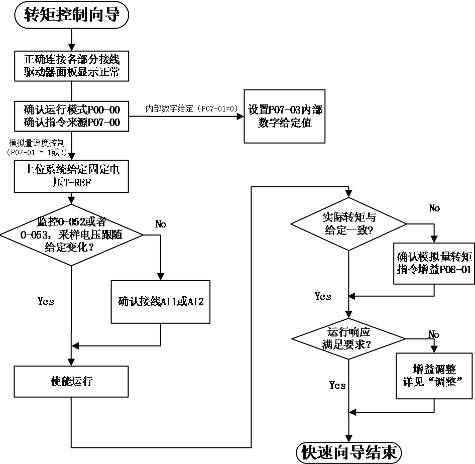
Figure 5-6 Torque Mode Usage Process
torque mode wiring
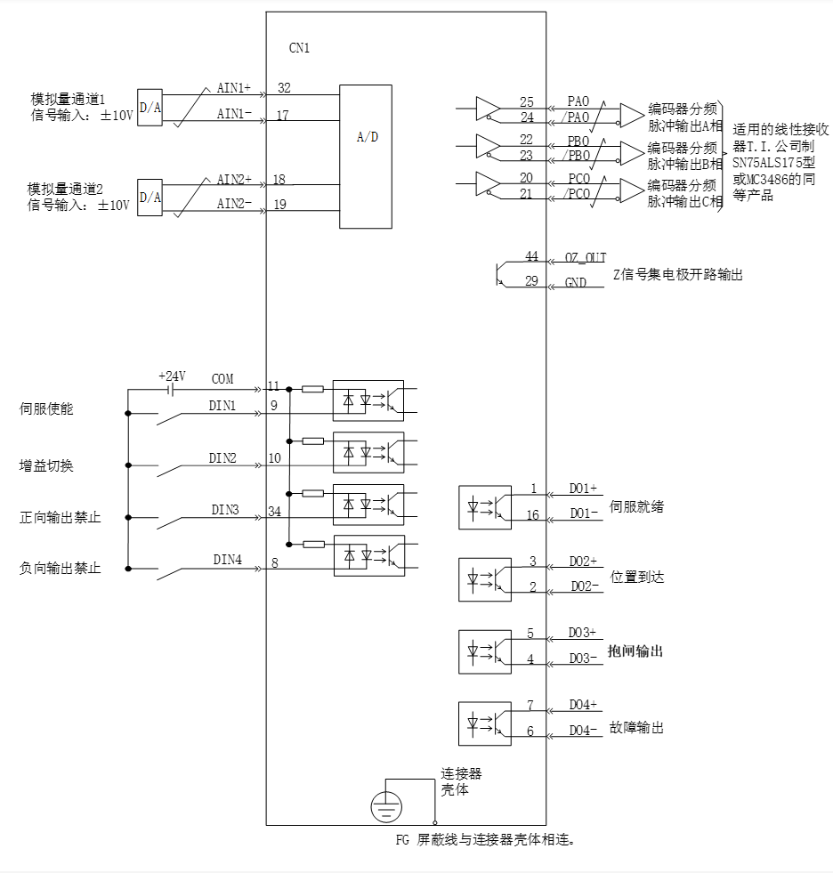 Figure 5-7 Torque Mode Wiring Diagram
 mean twisted pair cables
Note :
- Signal cables and power cables must be wired separately, with a minimum distance of 30cm between them;
- When connecting signal cables due to insufficient length, the shielding layer must be reliably connected and grounded;
- +5V is referenced to GND, and+24V is referenced to COM -. Do not exceed the maximum allowable current, otherwise the driver will not function properly
5.3.2Setting of torque mode related function codes
- Torque command input setting
- Source of torque command
In torque control mode, there are two sources of torque commands: source A and source B. There are two ways to set it:
- keyboard settings. The percentage of the torque value stored in function code P07-03 to the rated torque is used as the torque command.
- Analog command source refers to the conversion of external input analog voltage signals into torque command signals for controlling motors. At this point, the correspondence between analog quantities and torque commands can be arbitrarily specified.
Code | Name | Set range | unit | value | Effective Mode | Set mode | Relevant Mode |
P07-01 | Source of torque command A | 0 – Internal number given by P07-03 1 – AI1 2 – AI2 | - | 0 | Effective immediately | Stop set | T |
P07-02 | Source of torque command B | 0 – Internal number given by P07-03 1 – AI1 2 – AI2 | - | 0 | Effective immediately | Stop set | T |
P07-03 | Torque command digital set value | -300.0~300.0 | % | 0 | Effective immediately | Stop set | T |
- Torque command selection
The torque control mode has the following 5 ways to obtain torque commands, which are set through function code P07-00
Code | Name | Set range | unit | value | Effective Mode | Set mode | Relevant Mode |
P07-00 | Source of torque command A | 0- Torque command A 1- Torque command B 2- Torque command A+B 3- Torque command A/B switching 4- Communication Given | - | 0 | Effective immediately | Stop set | T |
- Direction switching of torque command
By setting the function code FunIN.25, DI can be used to control the direction switching of torque commands, meeting the needs of direction switching.
Code | Function name | description | Note |
FunIN.25 | Direction setting of torque command | valid-reverse direction Invalid - forward direction | The recommended logic selection for the corresponding terminal is to set it as: current level valid |
When the torque command selects "A/B switching",that is H07-02=3, a separate function definition needs to be assigned to the DI terminal. Select whether the current input of command A or B is valid through this input terminal.
Code | Function name | description | Note |
FunIN.4 | Command switch | Invalid - The current running instruction is A Valid - The current running instruction is B | The recommended logic selection for the corresponding terminal is to set it as: current level valid |
Using AI1 as an example to illustrate the method of setting torque commands.
Code | Name | Set range |
1 | Set the source as analog AI1 input P07-00 = 0 P07-01 = 1 | Set the source of torque command。 |
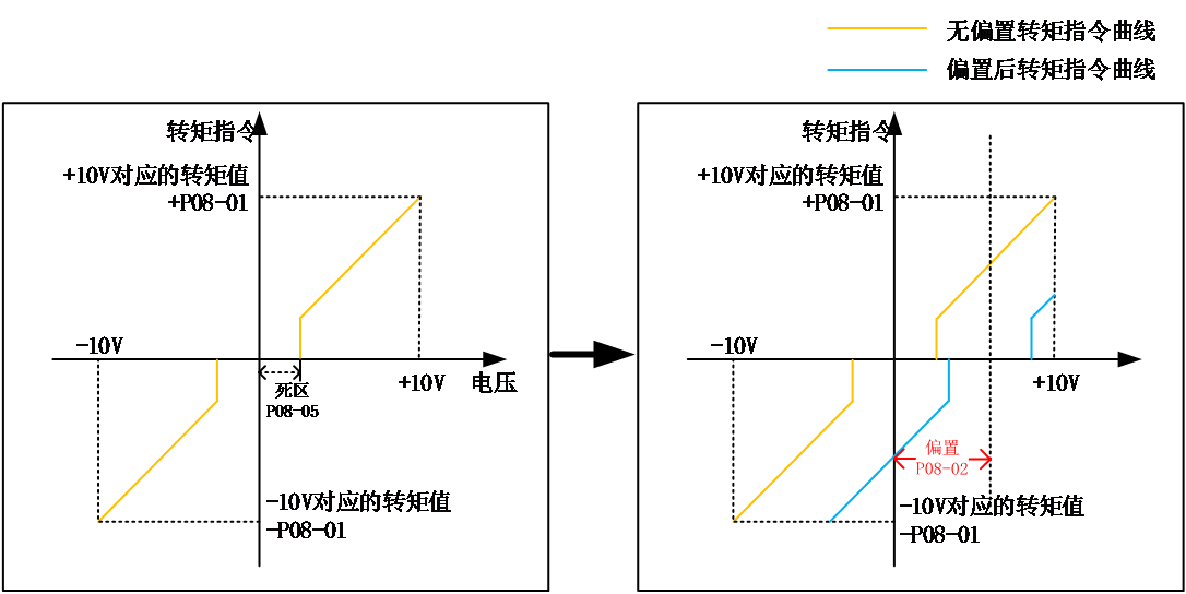
2 | Adjust AI1 related parameters:
| Through offset Dead zone setting, Adjust the sampling of AI1 |
3 | P08-01 Set the torque command value corresponding to 10V | Specify the maximum forward torque value corresponding to+10V Specify the maximum reverse torque value corresponding to -10V |
When there is interference in the AI1 input signal, the AI1 low-pass filtering parameter P08-03 can be set for filtering.
The given torque command (percentage relative to the rated torque of the motor) can be viewed through O-004.
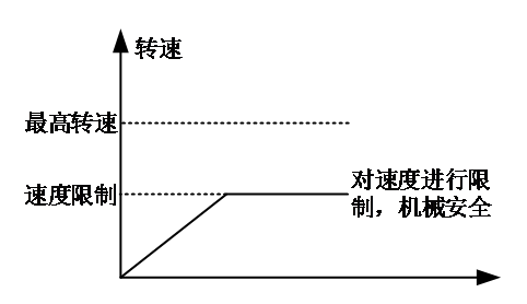
- Torque mode speed limit function
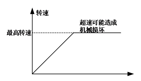
In torque control mode, to protect the machinery, it is necessary to limit the speed of the servo motor. When torque control is applied, the servo motor is only controlled by the output torque command and does not control the speed. Therefore, if the torque command is set too high, higher than the load torque on the mechanical side, the motor will continue to accelerate and overspeed. In this case, the speed limit value of the motor needs to be set.
When the speed exceeds the limit range, the speed difference between the overspeed and the limit speed is converted into a certain proportion of torque, which is cleared in the negative direction to return the speed to the limit range. Therefore, the actual motor speed limit value may fluctuate due to different load conditions. The speed limit value (speed instruction during same speed control) can be given through internal or analog sampling.
DO function selection: After the motor speed is limited, the output signal is as follows
Non speed limit | Speed limit |
|
|
Code | Function name | description |
FunOUT.9 | Speed limit signal | valid-motor speed limit invalid-motor speed non limit |
Note: The signal needs to be allocated to the corresponding digital output port.
The sources of speed limit include internal speed limit sources and external speed limit sources. When selecting the internal speed limit source (P07-12=0), directly set P07-13 to limit forward speed and P07-14 to limit negative speed. If P07-12=2, under FunIN.36 allocation, select P07-13 or P07-14 as the speed limit through DI. When P07-12=1 and selecting an external speed limit source, first specify the analog channel through P07-19, and then set the analog correspondence as needed. At this time, the external limit value should be smaller than the internal speed limit source to prevent danger caused by improper setting of the external speed limit source.
The speed limit method is set through the following function codes.
Code | Name | Set range | unit | value | Effective Mode | Set mode | Relevant Mode |
P07-12 | Speed limit source selection | 0- Internal speed limit 1- Use analog limit 2- Use V-SEL to select limit values | - | 0 | Effective immediately | Running set | T |
P07-19 | V-LMT selection | 0 – AI1 1 – AI2 | - | 1 | Effective immediately | Running set | T |
P07-13 | Internal speed forward limit value | 0~6000 | rpm | 3000 | Effective immediately | Running set | T |
P07-14 | Internal speed reverse limit value | 0~6000 | rpm | 3000 | Effective immediately | Running set | T |
- Torque command limit setting
To protect the mechanical device, the output torque can be limited by setting the function code P07-04. There are five ways to select torque limitation:
Code | Name | Set range | unit | value | Effective Mode | Set mode | Relevant Mode |
P07-04 | Source of torque limitation | 0- forward and reverse internal torque limit 1- forward and reverse external torque limitation (using P-CL and N-CL selection) 2- Use analog quantity to limit torque 3- forward and reverse external torque and analog limit torque (selected using P-CL and N-CL) 4- forward and reverse internal torque and analog limit torque (selected using P-CL and N-CL) | - | 0 | Effective immediately | 停机 设定 | T |
DI function selection: Input forward/reverse external torque limit selection signal P-CL/N-CL.
Code | Function name | description | Note |
FunIN.16 | Forward external torque limit | According to the selection of P07-04, switch the torque limit source. When P07-04=1: valid - The external torque limit for forward rotation is valid; Invalid - The internal torque limit for forward rotation is valid. When P07-04=3 and the AI limit value is greater than the external limit value for forward rotation: valid - The external torque limit for forward rotation is valid. Invalid - AI torque limit is valid. When P07-04=4: valid - AI torque limitation is valid; Invalid - forward internal torque limit is valid。 | The recommended logic selection for the corresponding terminal is to set it as: current level valid |
FunIN.17 | Reverse external torque limit | According to the selection of P07-04, switch the torque limit source. When P07-04=1: valid - Reverse external torque limitation is valid; Invalid - Reverse internal torque limit is valid. When P07-04=3 and the AI limit value is less than the reversal external limit value (negative comparison): valid - Reverse external torque limitation is effective; Invalid - AI torque limit is valid. P07-04=4: valid - AI torque limitation is valid; Invalid - Reverse internal torque limit is valid. |
DO function selection: Output torque limit confirmation signal C-LT。
Code | Function name | description | Note |
FunOUT.8 | Torque limit signal | valid – motor torque limit invalid – motor torque non limit |
Note: The signal needs to be allocated to the corresponding digital output port
For example, when setting up analog input AI, first specify the TLMT variable through function P07-18, and then set the corresponding relationship between torque and analog voltage.
When P07-04=1, the external torque limit for forward and reverse rotation is triggered by external DI settings (P-CL, N-CL), and torque is limited according to the values set for P07-07 and P07-08. When the external limits and their combination limits exceed the internal limits, the internal limits are taken, that is, due to the minimum limit value. The torque is limited within the maximum torque range of the motor. The TLMT is symmetrical, with a limit of | TLMT | value for forward rotation and reverse rotation
Code | Name | Set range | unit | value | Effective Mode | Set mode | Relevant Mode |
P07-04 | Source of torque command A | 0- forward and reverse internal torque limit 1- forward and reverse external torque limitation (using P-CL and N-CL selection) 2- Use analog to limit torque 3- forward and reverse external torque and analog limit torque (selected using P-CL and N-CL) 4- forward and reverse internal torque and analog limit torque (selected using P-CL and N-CL) | - | 0 | Effective immediately | Stop set | PST |
P7-18 | T-LMT selection | 0 – AI1 1 – AI2 | - | 0 | Effective immediately | Stop set | PST |
P07-05 | Internal torque limit value for forward rotation | 0.0~300.0 (100% =1x the rated torque ) | % | 300.0 | Effective immediately | Run set | PST |
P07-06 | Reverse internal torque limit value | 0.0~300.0 (100% =1x the rated torque ) | % | 300.0 | Effective immediately | Run set | PST |
P07-07 | forward external torque limit value | 0.0~300.0 (100% =1x the rated torque ) | % | 300.0 | Effective immediately | Run set | PST |
P07-08 | Reverse external torque limit value | 0.0~300.0 (100% =1x the rated torque ) | % | 300.0 | Effective immediately | Run set | PST |
- Torque reached
The torque arrival function is used to determine whether the actual torque value has reached the set interval. When the actual torque reaches the torque threshold, the driver will output the corresponding DO signal (FunOut.4: torque reached) for use by the upper controller.
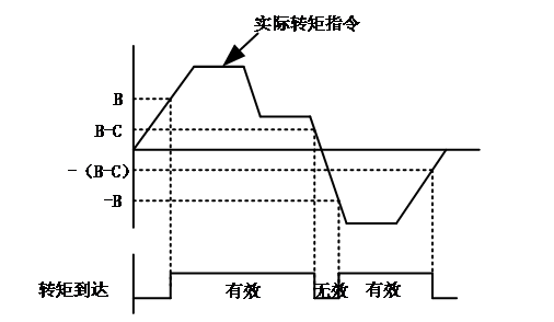
Actual torque command: A
Torque reaches reference value: B
Torque reaching hysteresis: C
When the torque reaches the DO signal from invalid to valid, the torque command needs to meet the following requirements:
|A| ≥ B
When the torque reaches the DO signal from valid to invalid, the torque command needs to meet the following requirements:
|A| < B – C
Otherwise, the torque reaches the DO signal and remains in its current state.
Note that it is necessary to ensure that B>C, otherwise hysteresis will not work.
Code | Name | Set range | unit | value | Effective Mode | Set mode | Relevant Mode |
P07-15 | torque reaches the reference value | 0~300.0 | % | 0.0 | Effective immediately | Run set | ALL |
P07-16 | Torque reaches hysteresis | 0~300.0 | % | 20.0 | Effective immediately | Run set | ALL |
DO Function selection: Output torque limit confirmation signal C-LT.
Code | Function name | description | Note |
FunOUT.4 | Torque reach signal | valid - The absolute value of the torque command is greater than the set value Invalid - The absolute value of the torque command is less than the set value |
Note: The signal needs to be allocated to the corresponding digital output port.