Adjustment
Adjustment refers to optimizing responsiveness by adjusting the servo gain of the servo unit.
The servo gain is set through a combination of multiple parameters (speed loop gain, position loop gain, filter, inertia ratio, etc.), which will affect each other. Therefore, when setting, the balance between the set values of each parameter must be considered.
The factory setting for servo gain is a basic setting. Please use various adjustment functions based on the user's mechanical condition to further improve responsiveness.。
Safety precautions during adjustment
When making adjustments, please set the servo unit protection function as shown in the following items under appropriate conditions.
(1) Set over travel
Please set the over travel. For detailed information, please refer to the relevant chapters.
(2) Setting of torque limit
The torque limiting function is to calculate the required torque for mechanical operation and limit the output torque to ensure it does not exceed that value. In the event of mechanical interference or collision, the impact can be reduced. If the torque is set below the required value for operation, overshoot or vibration may occur. Please refer to the relevant chapters for details.
(3) Set the alarm value for excessive position deviation
The alarm for excessive position deviation is an effective protection function when using servo units for position control.
When the motor action does not match the command, setting an appropriate position deviation alarm value can detect abnormal situations and stop the motor from running。
Basic Process of Adjustment
The figure below is a flowchart of the basic adjustment steps. Please make appropriate adjustments based on the status and operating conditions of the machine being used.
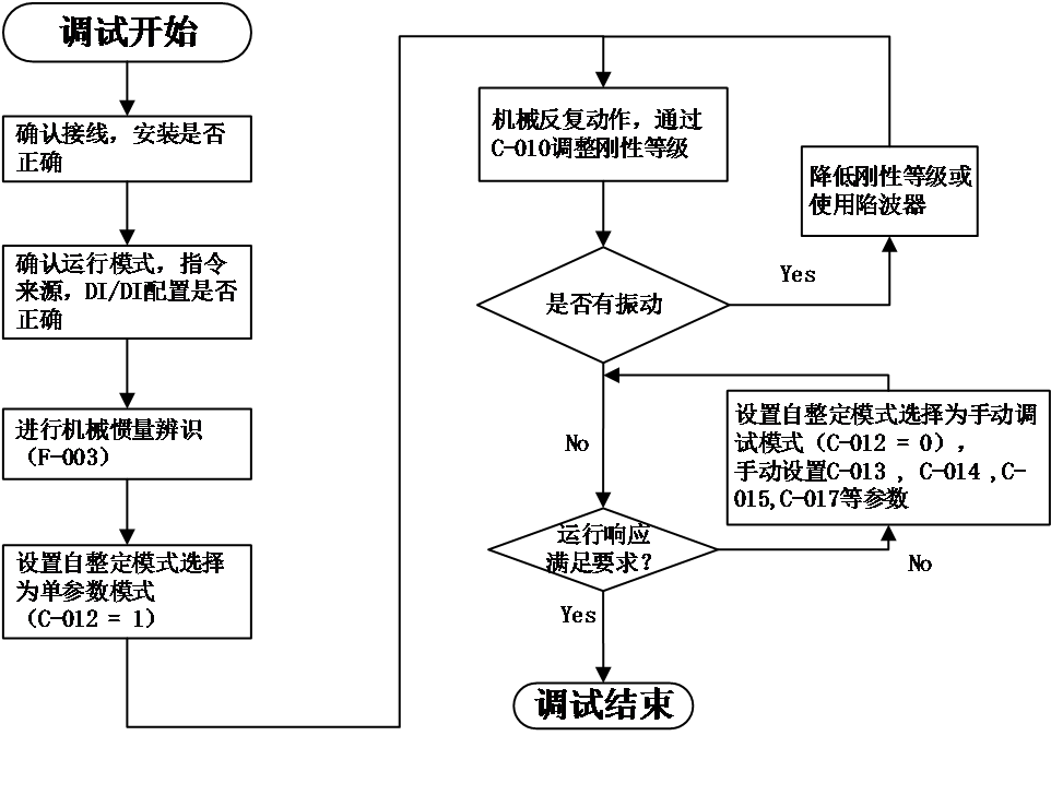
Figure 5-8 debug relevant methods
Firstly, check the wiring and installation correctly, and after setting the relevant basic functional parameters, adjust the inertia identification, single parameter adjustment, and vibration suppression performance.
Accurately setting the inertia ratio is the foundation of debugging. After obtaining the correct load inertia ratio through inertia identification, first set single parameter adjustment (see relevant chapters for details). If the effect is not good, then manually adjust the gain (see relevant chapters for details). Mechanical resonance can be suppressed by setting appropriate notch filters (see relevant chapters for details).
single parameter adjustment
Single parameter adjustment refers to adjusting the rigidity level of the servo through a single parameter (C-010), and the servo driver will automatically generate a set of matching gain parameters to meet the requirements of stability, accuracy, and speed.
Before starting single parameter adjustment, it is necessary to identify the load inertia or obtain relevant load parameters through manual calculation.
The range of values for the rigidity level (C-010) is between 0-31. Level 0 corresponds to the weakest rigidity and the smallest gain; Level 31 corresponds to the strongest rigidity and maximum gain. Based on different types of loads, the following experience can be used as a reference:5-8 levels, some complex transmission machinery.Level 9-14, systems with low rigidity such as belt drive and cantilever structure.Level 15-20, systems with high rigidity such as ball screws, gear racks, and direct drive systems
relevant function code as below::
Code | Name | Set range | unit | value | Effective Mode | Set mode | Relevant Mode |
C-012 | Self tuning mode selection | 0- Manual adjustment of gain mode 1- Single parameter adjustment mode 2- Single parameter adjustment mode (emphasizing position response) | - | 1 | Effective immediately | Run set | ALL |
C-010 | Rigid grade selection | 0~31 | - | 12 | Effective immediately | Run set | ALL |
Manual Adjustment Function
When single parameter adjustment still cannot meet the operational response requirements, the self-tuning mode (C-012) can be set to 0 to obtain better response through manual adjustment.
When manually adjusting the servo gain, please adjust each servo gain one by one based on understanding the composition and characteristics of the servo unit. In most cases, if a parameter undergoes significant changes, other parameters must be adjusted again. In order to confirm the response characteristics, it is necessary to prepare for observing the output waveform of the analog monitor using measuring instruments.
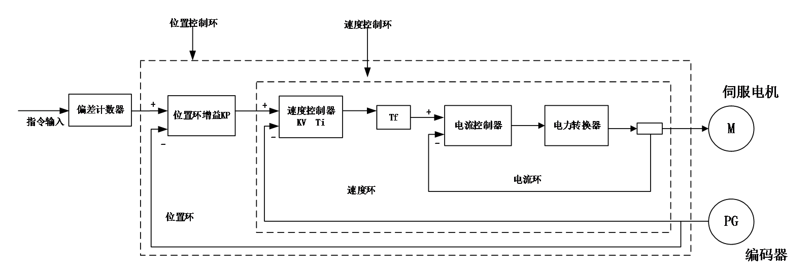
Figure 5.10 Manually adjust the control diagram
The servo unit consists of three feedback loops (position loop, velocity loop, current loop), and the more inner the loop, the more it needs to improve its responsiveness. If this principle is not followed, it will result in decreased responsiveness or vibration.
Due to the current loop ensuring sufficient responsiveness, users do not need to make adjustments.
Code | Data name | Debug principal |
C-015 | Position loop gain | The default value is 40.0Hz Adjust according to the positioning time The larger the value, the shorter the positioning time, but if it is too high, it can cause vibration |
C-013 | Speed loop gain | The default value is 25.0Hz Within the range where the mechanical system does not vibrate, the larger the set value, the more stable and responsive the servo system is When abnormal noise or vibration occurs, reduce it |
C-014 | Speed loop integral time constant | The default value is 31.83ms When the value is adjusted, the positioning time becomes faster, and if it is too small, vibration will occur When the value is large, it may cause the pulse deviation , not able reduced to zero |
C-017 | Torque command filtering time constant | The default value is 790us Try changing this value when vibration occurs The smaller the value, the more responsive control can be achieved |
P03-14 | Speed feed forward gain | The default value is 0.0% Increasing the feed forward gain can reduce real-time position deviation. When the input command is uneven, increasing the feed forward filtering time constant P03.13 can improve it When vibration occurs, try reducing this value |
The general method for manual adjustment is as follows:
Feed forward gain
Speed feed forward can be applied to position control mode and fully closed-loop function. The use of speed feed forward function can improve speed command response and reduce position deviation at fixed speeds。
Operation steps for speed feed forward function:
- Set the source of speed feed forward signal
Set P3-12 (speed feed forward control selection) to a non-zero value, the speed feed forward function will take effect, and the corresponding signal source will be selected;
Code | Name | Set range | unit | value | Effective Mode | Set mode | Relevant Mode |
P03-12 | Selection of position feed forward control | 0- No speed feed forward 1. Internal speed feed forward 2-AI1 as speed feed forward input 3-AI2 as speed feed forward input | - | 1 | Effective immediately | Stop set | P |
- Set speed feed forward parameters:
Including speed feed forward gain (P3-14) and speed feed forward filtering time constant (P3-13).
Code | Name | Adjust description |
P3-13 | speed feed forward filtering time constant | 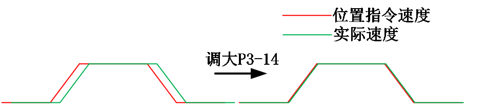 Parameter function: Increasing P3-14 can improve response, but may result in speed overshoot during acceleration and deceleration; Increasing P3-13 can suppress noise caused by uneven position commands, while reducing P3-13 can reduce speed overshoot during acceleration and deceleration. |
P3-14 | speed feed forward gain |
Mechanical vibration suppression
Mechanical systems have a certain resonance frequency. When the servo gain is increased, resonance may occur near the mechanical resonance frequency, causing the gain to be unable to continue to increase. Suppressing mechanical resonance can be achieved through the following two ways:
- Torque command filter (C-017)
By setting a filtering time constant, the torque is attenuated in the high-frequency range above the cutoff frequency, thereby achieving the goal of suppressing mechanical resonance
Code | Name | Set range | unit | value | Effective Mode | Set mode | Relevant Mode |
C-017 | Torque command filtering time constant | 0~3000 | 10us | 79 | Effective immediately | Run set | PST |
- Notch filter
The torque command filter is a digital band stop filter, with four sets of series notch filters available for selection. The first and second notch filters are manual notch filters, and the parameters are manually set by the user. The 3rd and 4th notch filters are adaptive filters, and their mode is controlled by P0E.00. You can choose whether to enable the 3rd (P0E-00=1) or enable both the 3rd and 4th (P0E-00=2) filters at the same time. When the adaptive filter mode is enabled, the filter parameters are set by the driver. If the (P0E-00=0) adaptive filter is not enabled, the filter parameters can be manually set.
Relevant code:
Code | Name | Set range | unit | value | Effective Mode | Set mode | Relevant Mode |
P0E-00 | Adaptive notch filter mode selection | 0- No action 1- Enable 1 adaptive filter (Group 3) to automatically update filter parameters 2- Enable 2 adaptive filters (groups 3 and 4) to automatically update filter parameters 3- Only detect resonance frequency, do not update filter parameters 4- Reset adaptive filter parameters | - | 0 | Effective immediately | Run set | PS |
P0E-01 | Frequency of notch filter 1 | 50~4000 | Hz | 4000 | Effective immediately | Run set | PS |
P0E-02 | Width level of notch filter 1 | 0~20 | - | 2 | Effective immediately | Run set | PS |
P0E-03 | Attenuation level of notch filter 1 | 0~99 | - | 0 | Effective immediately | Run set | PS |
P0E-04 | Frequency of notch filter 2 | 50~4000 | Hz | 4000 | Effective immediately | Run set | PS |
P0E-05 | Width level of notch filter 2 | 0~20 | - | 2 | Effective immediately | Run set | PS |
P0E-06 | Attenuation level of notch filter 2 | 0~99 | - | 0 | Effective immediately | Run set | PS |
P0E-07 | Adaptive notch filter 1 frequency | 50~4000 | Hz | 4000 | Effective immediately | Run set | PS |
P0E-08 | Adaptive notch filter 1 width level | 0~20 | - | 2 | Effective immediately | Run set | PS |
P0E-09 | Adaptive notch filter 1 attenuation level | 0~99 | - | 0 | Effective immediately | Run set | PS |
P0E-10 | Adaptive notch filter 2 frequency | 50~4000 | Hz | 4000 | Effective immediately | Run set | PS |
P0E-11 | Adaptive notch filter 2 width level | 0~20 | - | 2 | Effective immediately | Run set | PS |
P0E-12 | Adaptive notch filter 2 attenuation level | 0~99 | - | 0 | Effective immediately | Run set | PS |
P0E-13 | Identification results of resonance frequency | - | Hz | - | - | display | PS |