1. Electronic cam ECAM
1. Electronic cam ECAM
1.1. Instruction Description
In industries such as steel cutting, traditional methods often use the method of stopping cutting, which is inefficient and may not necessarily meet the requirements of the material's forming process. For industries such as packaging and printing that require real-time phase tracking of shafts, traditional industries often use mechanical camshafts to achieve this.
1.1.1. Mechanical cam and electronic cam
As shown in Figure 1.0, the shaft that drives the cam to rotate is the main shaft, and the shaft that drives the cam to move is the slave shaft. The main shaft corresponds to a certain position of the slave shaft at any position, and this correspondence depends on the contour curve of the cam, essentially reflecting a certain functional relationship between the main shaft position and the slave shaft position. In actual machining, when users use a cam, not the entire cam curve plays a critical role in the machining process. Often, it is certain points or line segments that play a decisive role in the machining process. By using these points and line segments, combined with appropriate mathematical models, a functional relationship between the master and slave axis positions can be established. Based on the current position of the main axis, calculate the corresponding position of the sub axis, and send pulses through the PLC to drive the sub axis mechanism to move to the corresponding position, thus achieving the function of running the sub axis according to the cam trajectory. This is the working principle of electronic cam.
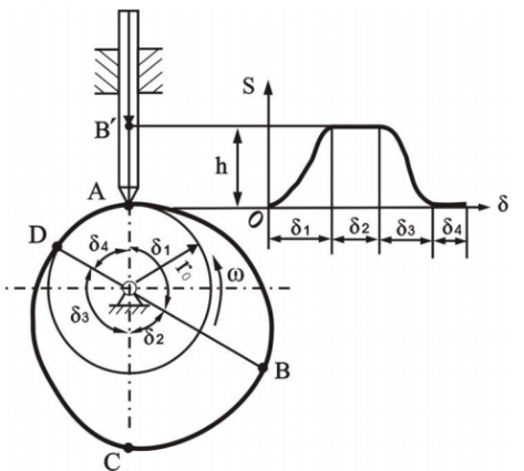
图1 Mechanical Cam
Compared with mechanical cams, electronic cams are more flexible, easier to modify curves, and greatly reduce maintenance costs. At present, there are three modes of electronic cam commands for display and control: chase shear, flying shear, and universal cam. Among them, chase shear and flying shear are two special application scenarios of universal camshafts, which are used in fields such as profile cutting and fixed length paper cutting. The universal cam can generate any irregular cam curve through the control of key points, making its usage scenarios more flexible. For these three modes, the display control ECAM command provides an interactive graphical interface to set parameters, as well as preview and adjust the automatically generated electronic cam motion curve.
1.1.2. Overview of Follow up Cutting
In the feeding and cutting of profiles, paper tubes, etc., traditional processes often use the method of stopping cutting, which is inefficient. The electronic cam follow-up cutting function realizes real-time tracking of the spindle movement from the shaft cutting table. During the movement, the synchronous zone is used for cutting and cutting, then the speed is reduced to 0, and then quickly returns to the origin, waiting for the next follow-up movement. This can ensure uninterrupted feeding of the spindle and improve production efficiency.
The trimming module consists of four parts: spindle feeding drive, spindle position feedback, linear following from the axis, and cutting module. The main spindle feeding drive mechanism is often composed of servo or frequency converter, and the main spindle position feedback mechanism is mainly composed of encoder, which feeds back the current position and speed of the main spindle. The linear following mechanism from the axis is often driven by servo through a screw to move the cutting module. The cutting module is mainly driven by air pressure, hydraulic or servo. Compared to solidifying the trimming program into the servo, implementing the trimming function in PLC is more convenient for modification. Combined with the easy application characteristics of PLC, the ECAM instruction of the display and control PLC is more convenient and fast to use. The schematic diagram of the structure of the shearing system is shown in Figure 1.2.
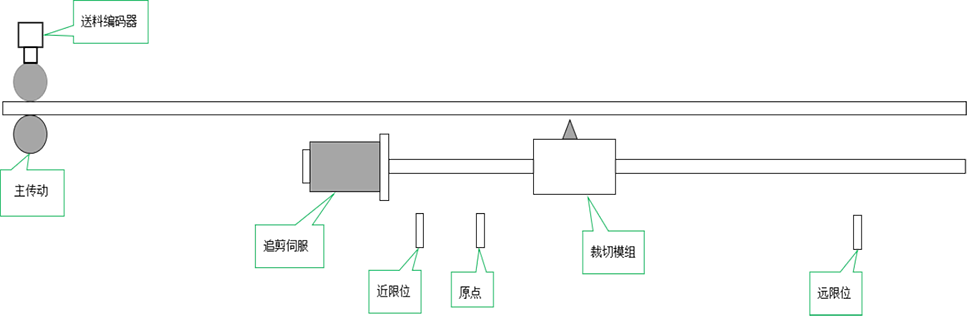
图2 Follow up editing process
The main transmission part is driven by servo or frequency converter to feed the pressure roller, and the position and speed of the feed are fed back by the encoder connected to the high-speed counter of the PLC. The cutting servo receives the pulse signal from the pulse port set in the cutting function, drives the cutting module to reach the corresponding cam curve position of the slave shaft, and the cutting module cuts according to the synchronization zone mark. The origin signal is used for resetting the cutting table, and the limit is used for stroke protection limit.
Trimming requires configuring the cutting length, and automatically generating trimming curves based on curve parameters and various mechanical parameters. The curve consists of four segments, namely acceleration zone, synchronization zone, deceleration zone, and reverse zone. The schematic diagram of the four curves is shown in Figure 1.3.
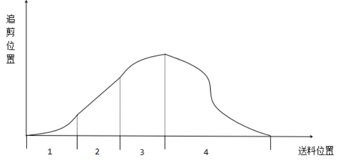
图3 Cutting Curve
The horizontal axis represents the distance traveled by the main axis, while the vertical axis represents the actual position of the axis
Acceleration zone: The length of this zone represents the distance traveled by the main axis during the acceleration process
Synchronization zone: The length of this zone represents the distance traveled by the spindle during the synchronous movement of the axis and spindle. The distance traveled by the axis and spindle in this zone is the same
Deceleration zone: This zone represents the distance traveled by the main shaft during the deceleration process
Reverse zone: This zone represents the distance traveled by the main axis during the process of returning to the origin in reverse from the axis
Calculation formula:
Material length=acceleration+synchronization+deceleration+reverse
Synchronization zone=synchronization speed * cutting time (when the spindle speed is stable, the synchronization speed is the spindle speed. The cutting time should be greater than the actual cutting time)
Attention:
The larger the acceleration and deceleration zones, the smoother the acceleration and deceleration from the axis. When the material length is constant, the size of the acceleration and deceleration zone will affect the length of the synchronization zone, and the length of the synchronization zone needs to ensure that it can meet the normal cutting requirements.
1.1.3. Overview of Flying Scissors
In industries such as fixed length paper cutting and packaging cutting, the flying shear can make the rotation of the flying shear wheel follow the spindle motion in real time. The feeding encoder is connected to the PLC high-speed counter to feedback the spindle position and speed. At the same time, the flying shear servo receives the pulse signal specified in the ECAM instruction and drives the flying shear wheel to reach the corresponding sub axis position of the cam curve. When the photoelectric origin signal is detected, the cutting blade is at the starting position, as shown in Figure 1.3, which is a schematic diagram of the flying shear structure.
The module of the flying shear consists of three parts: spindle feeding drive, spindle position feedback, and flying shear wheel. The main spindle feeding drive mechanism is often composed of servo or frequency converter, and the main spindle position feedback mechanism is mainly composed of encoder, which feeds back the current position and speed of the main spindle. The flying shear wheel is usually driven by servo. The schematic diagram of the flying shear system structure is shown in Figure 1.3.
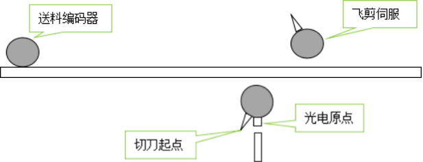
图4 Flying Cutting Process
The flying shear wheel automatically generates a flying shear curve by configuring parameters such as cutting length, acceleration zone, synchronization zone angle, and number of cutting blades. The motion trajectory of the flying shear wheel is divided into three areas: acceleration zone, synchronization zone, and deceleration zone. The trajectory division of the flying shear wheel is shown in Figure 1.5.
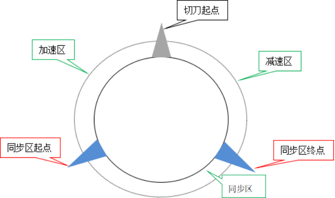
图5 Trajectory division of flying shear wheel
The motion curve of the flying shear is shown in Figure 1.6:
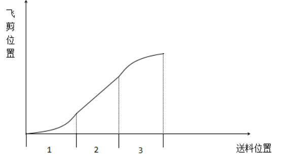
图6 Flying Shear Curve
The horizontal axis represents the distance traveled by the spindle, and the vertical axis represents the actual angle of the flying shear wheel (the starting point of the cutting blade is 0 °)
Acceleration zone: The length of this zone represents the distance traveled by the main axis during the acceleration process
Synchronization zone: The length of this zone represents the distance traveled by the spindle during synchronous motion from the axis to the spindle. The length of the line rotated by the flying shear wheel in this zone is the same as the distance traveled by the spindle
Deceleration zone: This zone represents the distance traveled by the main shaft during the deceleration process
1.1.4. Overview of Universal Cams
Chasing shears and flying shears are common cam applications, and there are many electronic cam application requirements based on the different positions of the master and slave axes. The ECAM command provides a universal electronic cam function, which can configure custom cam curves through key point coordinates and line segment parameters.
Customizing a cam requires setting various key point parameters, each consisting of four parameters: main axis coordinates, sub axis coordinates, target slope, and line type. The position of the key point can be determined by its coordinates, and the shape of the curve can be determined by its slope and line type, thus forming a user-defined cam curve.
Take the following five key points【0,0,0,0】【100,50,0.5,1】【300,400,-1.5,0】【500,100,-1.5,1】【600,400,0.5,0】,Can form a custom curve as shown in Figure 1.7:
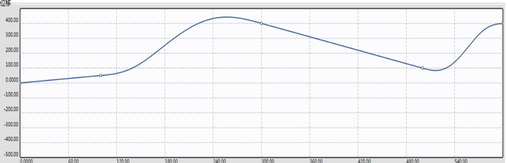
图7 Universal Cam Curve
Operation process description:
The first paragraph: When the spindle runs from 0 to 100, it runs from 0 to 50. Based on the endpoint slope of 0.5 and the running curve of this paragraph being a straight line, when the spindle runs at a constant speed, it runs from half the spindle speed to 50
Second paragraph: When the spindle runs from 100 to 300 and from 50 to 400, the curve in this paragraph is a spline curve with a slope of -1.5 at the endpoint. The axis runs in a sine curve to the position of 400
The third paragraph: When the spindle runs from 300 to 500 and from 400 to 100, according to this paragraph, it is a straight line with a slope of -1.5, and runs at a constant speed from the axis to the position of 100
The fourth paragraph: When the spindle runs from 500 to 600 and from 100 to 400, this paragraph is a spline curve with a slope of 0. The spindle runs in a sine curve to the position of 400
When the main shaft passes the end point of the fourth section, it continues to run according to the cam curve from the end position of 400 as the reference, and this cycle is repeated.
1.2. Parameter configuration
The parameters of ECAM electronic cam can be divided into two parts, one is the general parameters, and the other is the parameters under different modes. The parameter settings are unreasonable, the cam will not operate, and there will be a corresponding error code 46 in the error code register D8176. The possible situation of parameter errors is described in detail in Note 2 of this paragraph.
1.2.1. Port configuration and general parameters
General parameters are divided into four types: basic parameters, compensation coefficients, operating state parameters, and follow-up coefficients.
1.2.2. Basic parameter
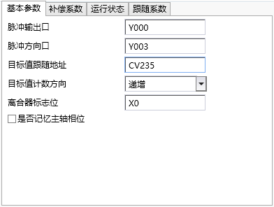
图8 Basic parameter
Note: Data type and register type
INT32 represents a 32-bit signed integer, UINT32 represents a 32-bit unsigned integer, FP32 represents a 32-bit floating-point number, INT16 is a 16 bit signed integer, UINT16 is a 16 bit unsigned integer, and BOOL represents a flag bit
R read-only, W write only, R/W readable and writable, unit pls represents the number of pulses
In this instruction, register type Y represents Y pulse output port bit register, D represents double word D register, K represents constant, CV represents high-speed counter register, X represents input port bit register, and M represents internal M-bit register
| Parameter Type | Parameter Name | Data Type | Register Type | Default Value | Value Range | Unit | ||
|---|---|---|---|---|---|---|---|---|
| :------------: | :--------------: | :------: | :--------: | :----- | :------: | :--: | ||
| Pulse related | Pulse output port | Y | ||||||
| Pulse direction port | Y | |||||||
| Follow target value | Follow target value address | D/CV | ||||||
| Target value counting direction | Increasing | |||||||
| Clutch related | Clutch logo | X/M | ||||||
| Other | Memory of spindle phase | No | ||||||
| Parameter Name | Remarks | |||||||
| Pulse output port | Y port on PLC for outputting pulses from axis servo | |||||||
| Pulse direction port | Y port on PLC for servo output direction from the axis | |||||||
| Follow the target value address | Record the relevant registers of the spindle position, currently can input D or high-speed counter CV | |||||||
| Target value counting direction | Increasing or decreasing value of target value address during spindle advancement | |||||||
| Clutch flag position | Currently only supports X/M. Please ensure that the main PLC has the corresponding X port when selecting X (supports IO expansion board X port, does not support X port on expansion module, and X port requires a certain filtering time to prevent interference) (Note 5) | |||||||
| Whether to remember the main axis phase | The selection represents that after the ECAM command is reactivated, it will start running according to the main and secondary axis phases of the last deactivation; Choosing 'No' means that after re enabling, the master and slave axis phase records before clearing will be cleared (all operating parameters will be cleared), and the operation will start from scratch |
1.2.3. Compensation coefficient
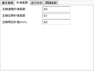
图9 Compensation coefficient
| Parameter Type | Parameter Name | Data Type | Register Type | Default Value | Value Range | Unit |
|---|---|---|---|---|---|---|
| Compensation coefficient | Spindle speed compensation coefficient | FP32/W | D/K | 0 | -100:100 | |
| Spindle displacement compensation coefficient | FP32/W | D/K | 1 | 0.9:1.1 | ||
| Spindle phase compensation | FP32/W | D/K | 0 |
| Parameter Name | Remarks |
|---|---|
| Spindle speed compensation coefficient | Due to algorithmic delay, the corresponding compensation amount can be calculated based on the current spindle speed. The program will automatically calculate an optimal compensation coefficient based on the tracking performance, which is the offset of the compensation coefficient. The input value is within ± 100 (Note 3) |
| Spindle displacement compensation coefficient | Due to algorithmic delay, the corresponding compensation amount can be calculated based on the current spindle speed. The program will automatically calculate an optimal compensation coefficient based on the tracking performance, which is the offset of the compensation coefficient. The input value is within ± 100 (Note 3) |
| Spindle phase compensation | Through phase compensation, the shear position can be moved forward or backward, which is equivalent to translating the cam position curve of the master and slave axes |
1.2.4. Operating status parameters
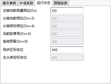
图10 Operating status parameters
The following parameters are read-only during operation and can be read and written after failure.
| Parameter Type | Parameter Name | Data Type | Register Type | Default Value | Value Range | Unit |
|---|---|---|---|---|---|---|
| Operating parameters | Spindle current measured phase | INT32/W/R | D | pls | ||
| From the current phase of the axis | INT32/W/R | D | pls | |||
| From axis target phase | INT32/W/R | D | pls | |||
| Current paragraph number | UINT32/W/R | D | ||||
| Synchronization Zone Flag (Flying Clipper) | BOOL/W/R | M | ||||
| Master slave axis binding flag (chasing fly cutting color code mode) | BOOL/W/R | M |
| Parameter Name | Remarks |
|---|---|
| The current measurement phase of the spindle | The position of the spindle within a phase cycle, and after crossing the cycle, the cycle begins again. Chasing flying shear: One spindle phase period is the number of encoder feedback pulses corresponding to the cutting length traveled by the spindle. Universal cam: The phase period is the number of pulses corresponding to the last key point spindle position. |
| From the current phase of the axis | From the position of the axis within one phase period, after reaching the end of one period, it will be reset. Chasing flying shear: The end point of the axial phase period of the chasing shear is 0, and the end point of the axial phase period of the flying shear is the number of pulses required for one rotation of the flying shear wheel. Universal cam: The phase period is the number of pulses corresponding to the axis position at the last key point. |
Follow the target position on the cam curve corresponding to the target phase of the main axis and the current position of the main axis.
| Current paragraph number | Current spindle running interval number. |
| Synchronization zone flag | The flag indicating that the master and slave axes in the chasing shear are within the synchronization zone, where 'on' represents being within the synchronization zone. |
| Master and slave axis binding flag | The flag for whether the master and slave axes are bound in the color code cutting mode of the chasing flying cutter, where 'on' represents the bound state. Always maintain an on state in all other modes. |
1.2.5. Follow coefficient
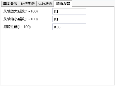
图11 Follow coefficient
| Parameter Type | Parameter Name | Data Type | Register Type | Default Value | Value Range | Unit |
|---|---|---|---|---|---|---|
| Follow coefficient | Axial amplification coefficient | INT32/W | D/K | 1 | 1-100 | |
| Reduction factor from axis | INT32/W | D/K | 1 | 1-100 | ||
| Follow performance | INT32/W | D/K | 50 | 1-100 |
| Parameter Name | Remarks |
|---|
The position of the camshaft corresponding to the proportional amplification cam curve based on the amplification factor of the shaft.
The axial position corresponding to the proportional reduction of the cam curve.
| Follow performance | Affects the stiffness of following the target value from the axis. The larger the value, the greater the stiffness, and the tighter the target value is followed from the axis. |
1.2.6. Cutting parameters
Cutting parameters are divided into three types: mechanical parameters, cutting parameters, and calibration parameters.
1.2.7. Mechanical parameters(trimming cut)
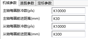
图12 Mechanical parameters (trimming)
| Parameter Type | Parameter Name | Data Type | Register Type | Default Value | Value Range | Unit |
|---|---|---|---|---|---|---|
| Mechanical coefficient | Number of pulses per revolution of spindle | UINT32/W | D/K | >0 | pls | |
| Distance per rotation of spindle | FP32/W | D/K | >0 | mm | ||
| Number of pulses per revolution from the axis | UINT32/W | D/K | >0 | pls | ||
| Distance per circle from the axis | FP32/W | D/K | >0 | mm |
| Parameter Name | Remarks |
|---|---|
| The number of pulses per revolution of the spindle | the number of pulses emitted per revolution by the spindle servo or feedback pulses per revolution by the spindle encoder. |
| The distance per revolution of the spindle | the actual distance of feeding when the spindle servo or encoder rotates one revolution. |
| Number of pulses per revolution from the axis | Number of pulses per revolution from the axis servo. |
| Distance per turn from axis | Number of pulses per turn from axis servo. |
1.2.8. Cutting parameters
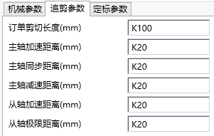
图13 Cutting parameters
| Parameter Type | Parameter Name | Data Type | Register Type | Default Value | Value Range | Unit |
|---|---|---|---|---|---|---|
| Cutting parameters | Order cutting length | FP32/W | D/K | >0 | mm | |
| Spindle acceleration distance | FP32/W | D/K | >0 | mm | ||
| Spindle synchronization distance | FP32/W | D/K | >0 | mm | ||
| Spindle deceleration distance | FP32/W | D/K | >0 | mm | ||
| Acceleration distance from axis | FP32/W | D/K | >0 | mm | ||
| From the axis limit distance | FP32/W | D/K | >0 | mm |
| Parameter Name | Remarks |
|---|---|
| Order cutting length | Fixed length mode: The actual cutting length of the material. Calibration mode: The minimum value of the cutting material length. |
| Spindle acceleration distance | The distance traveled by the spindle corresponding to the acceleration stage. |
| Spindle synchronization distance | The distance traveled by the spindle corresponding to the axis synchronization stage. |
| Spindle deceleration distance | The distance traveled by the spindle corresponding to the deceleration stage. |
| Distance from axis acceleration | The distance traveled during the axis acceleration phase. |
Maximum distance between the axis and the origin during operation.
1.2.9. Calibration parameters

图14 Calibration parameters
| Parameter Type | Parameter Name | Data Type | Register Type | Default Value | Value Range | Unit |
|---|---|---|---|---|---|---|
| Calibration parameters | Calibration settings | |||||
| Color code marker | X/M | |||||
| Color protection distance | FP32/W | D/K | 0 | >=0 | mm |
| Parameter Name | Remarks |
|---|---|
| Calibration setting | Fixed length mode: continuous cutting without pause in the middle. Calibration mode: Only start trimming after detecting the color code, and wait for the next color code to arrive before starting trimming. |
| Color code marker | The port on the PLC used to detect color code signals. (Supports IO expansion board X port, does not support X port on expansion module) |
| Color code protection distance | In calibration mode, after detecting a color code, it must pass through (order cutting length+color code protection distance) before it can be detected again. |
1.2.10. Flying shear parameters
Flying shear parameters are divided into three types: mechanical parameters, follow-up shear parameters, and calibration parameters.
The calibration parameters and trimming mode are exactly the same.
1.2.11. Mechanical parameters (flying shear)
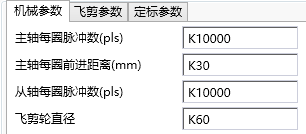
图15 Mechanical Parameters
| Parameter Type | Parameter Name | Data Type | Register Type | Default Value | Value Range | Unit |
|---|---|---|---|---|---|---|
| Mechanical coefficient | Number of pulses per revolution of spindle | UINT32/W | D/K | >0 | pls | |
| Spindle distance per turn | FP32/W | D/K | >0 | mm | ||
| Pulse count per revolution from axis | UINT32/W | D/K | >0 | pls | ||
| Flying shear wheel diameter | FP32/W | D/K | >0 | mm |
| Parameter Name | Remarks |
|---|---|
| The number of pulses per revolution of the spindle | the number of pulses emitted per revolution by the spindle servo or feedback pulses per revolution by the spindle encoder. |
| The distance per revolution of the spindle | the actual distance of feeding when the spindle servo or encoder rotates one revolution. |
| Number of pulses per revolution from the axis | Number of pulses per revolution from the axis servo. |
1.2.12. Flying shear parameters
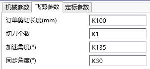
图16 Flying Clipper Parameters
| Parameter Type | Parameter Name | Data Type | Register Type | Default Value | Value Range | Unit |
|---|---|---|---|---|---|---|
| Flying shear parameters | Order cutting length | FP32/W | D/K | >0 | mm | |
| Number of cutting blades | INT32/W | D/K | >0 | |||
| Acceleration angle | FP32/W | D/K | 0~360/number of cutting blades | ° (degrees) | ||
| Synchronization angle | FP32/W | D/K | 0~360/number of cutting blades | ° (degrees) |
| parameter name | NOTE |
|---|---|
| Order cutting length | Fixed length mode: The actual cutting length of the material. Calibration mode: The minimum value of the cutting material length |
| Number of cutting blades | times of the flying shear wheel cut the material per rotation。 |
| Acceleration angle | Acceleration zone angle of the flying shear wheel |
| Synchronization angle | Synchronization zone angle of the flying shear wheel. |
1.2.13. General cam parameters
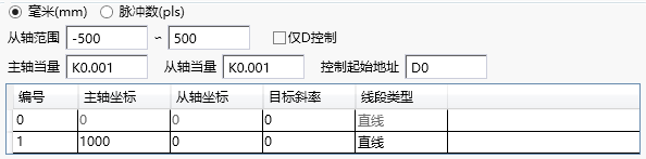
图17 General cam parameters
| Parameter Type | Parameter Name | Data Type | Register Type | Default Value | Value Range | Unit |
|---|---|---|---|---|---|---|
| Mechanical Parameters | Millimeters/Pulse Count | |||||
| From axis range | ||||||
| Spindle Equivalent | FP32/W | D/K | 0.001 | >0 | mm/pls | |
| From axis equivalent | FP32/W | D/K | 0.001 | >0 | mm/pls | |
| Key point parameters | Spindle coordinates | D/K | ||||
| From the axis coordinate | D/K | |||||
| Target slope | D/K | |||||
| Line segment type | ||||||
| Other | Only D control | |||||
| Control starting address |
1.2.14. Curve Preview Area
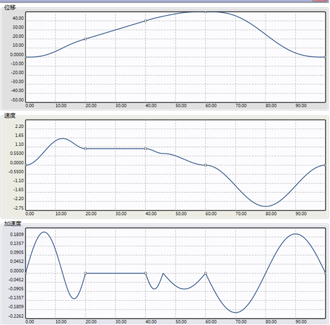
图18 Displacement/Velocity/Acceleration Curve
As shown in Figure 2.5: The main axis coordinates in the curve preview area represent the distance traveled by the main axis, while the sub axes represent the position, velocity, and acceleration of the sub axes. The curve can be automatically generated and adjusted by inputting parameters. According to the speed curve graph, parameter settings should strive to ensure a smooth transition from the axis speed at key points, and avoid situations where the speed is too high and the curve is too steep. The spindle speed can also be used to roughly determine the maximum speed of the axis, in order to determine whether to adjust the curve or reduce the spindle speed to avoid exceeding the speed limit.
1.3. Note
1.3.1. Calibration mode
If the detection distance between two color codes is greater than the cutting order length, the actual cutting length is the color code distance. If the detection distance of the color code is exactly equal to the cutting length of the order, the actual cutting distance is the cutting order length. If the detection distance of the color code is less than the cutting length of the order, the detection of the second color code will not work and will wait for the detection of the next color code. If the distance between the next color code and the starting color code is greater than the cutting length of the order, the color code will work. In this case, there may be one or more invalid color code signals between the two valid color codes.
1.3.2. Reasonable parameter settings
All parameter settings must not exceed the value range, and some parameters also need to meet the following relationship, otherwise it will cause parameter error alarm. The corresponding error code in D8176 is 46.
Speed up zone+synchronization zone+deceleration zone(cutting length
Chasing shear from axis acceleration distance+synchronization zone(Chasing shear from axis limit distance
Flying shear synchronous zone+acceleration zone<(360 °/number of cutting blades)
1.3.3. Three types of error compensation
1)Spindle speed compensation coefficient
Description: This compensation coefficient is mainly used to compensate for deviations proportional to speed. During the acceleration process, the greater the speed, the greater the deviation; The deceleration process is opposite; Stable deviation during uniform speed process; The schematic diagram of the relationship between deviation and spindle is shown in Figure 3.1:
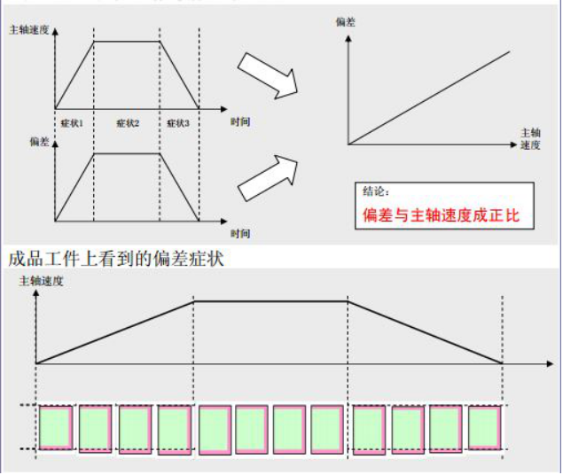
图19 Figure 3.1 Deviation Phenomenon
Reason: Due to the characteristics of electronic cam, there is a delay caused by processing time during the calculation process.
Solution: The program will provide a suitable algorithm delay time T internally. Based on the current spindle speed F, the spindle advance △=F * T that should be compensated can be calculated. This compensation amount will be added to each measured spindle position to achieve the purpose of compensation. The meaning of the speed compensation coefficient in the parameter is the offset adjustment amount of time T. Generally, it can be set to 0, and can be slightly adjusted left or right when needed.
2)Compensation coefficient for spindle displacement
Description: An increase in spindle movement will lead to an increase in synchronization deviation, as shown in Figure 3.2.
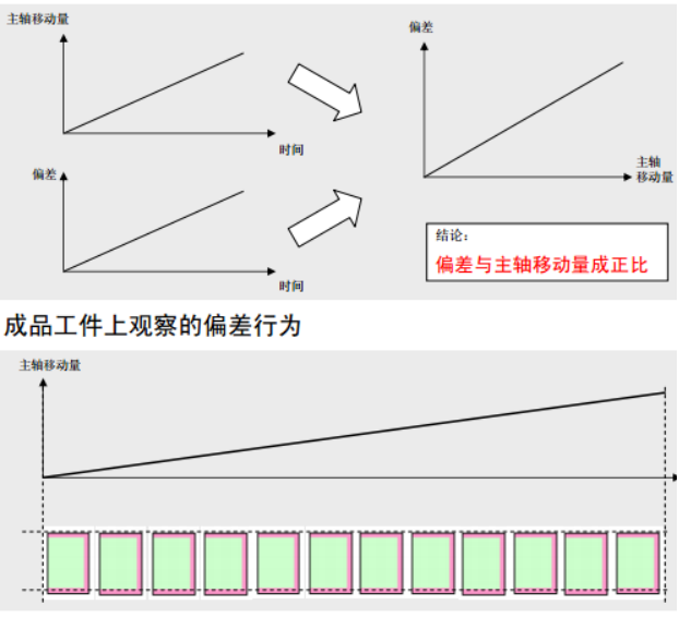
图20 Figure 3.2 Deviation Phenomenon
Reason: There is an error between the mechanical structure and the given value.
Example: The flying shear wheel advances in one circle. Example L=flying shear wheel diameter R * π. Due to π=3.14159265358979 ···· being an irrational number. When calculating in practice, π will take a certain number of digits, such as 3.14159265358979. When the diameter is 100m, there is an error of 0.000265368979 per circle. After 10000 circles, there is an error of 2.6536897mm, which cannot be ignored. This error will continue to increase as the total distance increases.
Solution: Due to the proportional relationship between the deviation and the total length, this proportional relationship can be obtained through experiments during actual operation. The total length L * proportion K=total length error compensation amount. Adding this compensation amount to the spindle position during operation can reduce the total length error caused by mechanical structural errors.
Note: In fixed length shearing, if the mechanical parameters are relatively accurate, the error compensation coefficient is very close to 1. If it is not necessary in the calibration cutting, it can be ignored and set as the default value of 1.
3)Spindle phase shear compensation
Description: Error that is not related to the magnitude of spindle movement or speed. The first cut deviated, causing an overall shift in the subsequent cutting position, as shown in Figure 3.3.
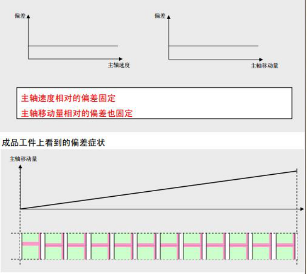
图21 Figure 3.3 Deviation Phenomenon
Reason: The positional relationship between the master and slave axes has deviated, which only affects the processing during the first run. However, if the cutting position for paper cutting needs to correspond to the scene of the pattern, this situation is completely not allowed to occur.
Solution: Always offset one initial phase during the operation of the spindle. Corresponding to the spindle phase compensation in the parameter, the compensation value is the deviation of the first blade. When the deviation is positive, it is sheared ahead of time, and when the deviation is negative, it is sheared behind time. As shown in Figure 3.4.
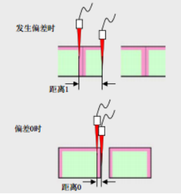
图22 Figure 3.4 Lag Shear
1.3.4. General cam parameter setting
The parameter setting of a universal cam needs to meet certain rules and may make some reasonable adjustments.
*If the counting direction of the spindle target value is increasing, then the spindle coordinates of this section must be greater than those of the previous section, otherwise it will cause an error.
*If the axis coordinates of this section are equal to those of the previous section, the slope of this key point will automatically adjust to 0.
*If the key point line type in this section is a straight line, the slope of this section will be automatically calculated by the ratio of the difference between the axis coordinates and the main axis coordinates. If the user input does not match, it will be automatically modified.
*If the key point in this section is a straight line and the line type of the previous key point is a spline, the slope of the previous key point will automatically adjust to the slope of this section of the straight line (ensuring a smooth transition).
1.3.5. Clutch
The clutch flag can be used to register X or M bits. Setting the clutch flag can break the binding relationship between the master and slave shafts without the need for a disconnection command, allowing for the use of other pulse commands to control the movement of the slave shaft. When resetting the clutch, the master and slave shafts will start moving from the main shaft position when disconnected and the corresponding slave shaft position.
Attention: When setting the clutch, unless absolutely necessary, it is recommended that the main shaft does not shift during the effective period of the clutch. Otherwise, after the clutch is reset, the length of the first blade will shift accordingly. At the same time, if other pulse commands are used on the slave shaft, the corresponding pulse command must be disconnected before resetting the clutch flag position. Otherwise, the master and slave shafts will not be successfully bound. If the slave shaft deviates when the clutch is activated, the synchronization zone and the origin position will also be offset. For shear cutting, changing the origin position will cause the entire stroke to shift, which may lead to exceeding the limit. During the effective period of the clutch, if a disable command is given and the main shaft phase is not memorized, re enabling it will start running again from the initial position of the main shaft, which may result in an overall deviation from the range of shaft travel.
1.3.6. Operating parameters
The operating parameters consist of consecutive doubleword D registers and M-bit registers. If the user wishes to save the current running position even after the instruction is disabled, they can set these registers within the power-off hold range. This way, when re enabled, the ECAM will automatically start running from the positions recorded in these registers instead of starting over from scratch. If the user has selected the memory spindle position and wishes to clear the ECAM data from scratch, they can choose to disable the ECAM, clear this series of registers in the ladder diagram, and then re enable it to start running from scratch.
The operating parameters are read-only during ECAM operation, and can be read and written after failure
1.4. Application
This chapter mainly introduces the steps and some key precautions for using ECAM instructions.
1.5. The application of chasing flying scissors
Debug process:
Check if the PLC pulse port is normal, if the servo is working properly, and if the wiring is correct.
Configure the pulse port and target value address. Confirm whether the target value corresponding to the forward direction of the spindle is increasing or decreasing. Configure the clutch flag bit, which can be obtained by using the external clutch signal from the X port or mapping it to the internal M register. Confirm whether it is necessary to record the phase of the current master and slave axes when the command fails. If it is necessary to record the phase of the current master and slave axes, the first address of the operating parameters should be set in the power-off hold area. This way, after power failure, the command can restart from the last power-off position when powered on again. Otherwise, it will restart from the initial position.
The mechanical parameters of the chasing shear, such as the number of pulses per turn and the forward distance per turn, need to be configured as accurately as possible, otherwise it will affect the cutting length or synchronization zone.
Choose between calibration mode and fixed length mode based on the actual situation, and set the parameters for follow-up cutting or flying cutting according to the actual situation.
1) Chasing Cutting
On the premise of meeting the requirement for parameter legality (see parameter introduction in Part 2), the purpose of the trimming parameters is to ensure smooth acceleration and deceleration during shaft operation, with sufficient synchronization distance to complete the trimming action. The relationship diagram of the trimming parameters is shown in Figure 4.1.
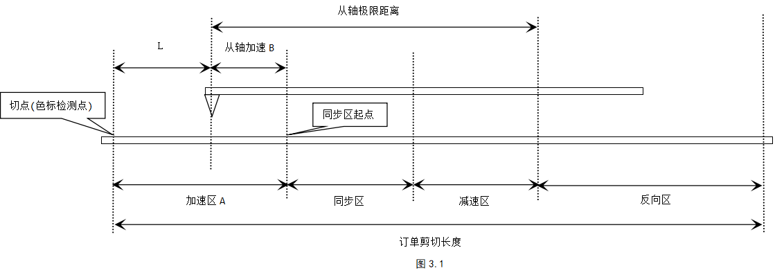
图23 Figure4.1 chasing cutting example
Assuming the distance between the main axis acceleration zone is A and the acceleration distance from the axis is B. When the axis is located at the starting point, the distance between the tangent point and the starting point is L, then L=A - B. At this point, the tangent point position is known, and according to the size relationship between A and B, the tangent point position may be on different sides of the starting point. The deceleration zones and the maximum distance from the axis in the remaining synchronization zones are set according to the actual situation while ensuring a smooth speed curve.
If the fixed length mode is selected, the material length can be controlled during the first cutting according to the cutting point position.
If the calibration mode is selected, when the axis is at the starting position, if the punctuation mark is at the cutting point position, then the punctuation mark is the cutting point. When the position of punctuation marks is adjustable, they can be appropriately offset according to the actual situation.
2) Flying scissors
On the premise of meeting the requirement of parameter legality (see the parameter introduction in Part 2), the purpose of the flying shear parameters is to ensure that the rotary cutting shaft accelerates and decelerates smoothly during operation, and has sufficient synchronization zone distance to complete the cutting action. The schematic diagram of the relationship between the parameters of the flying shear is shown in 4.2.
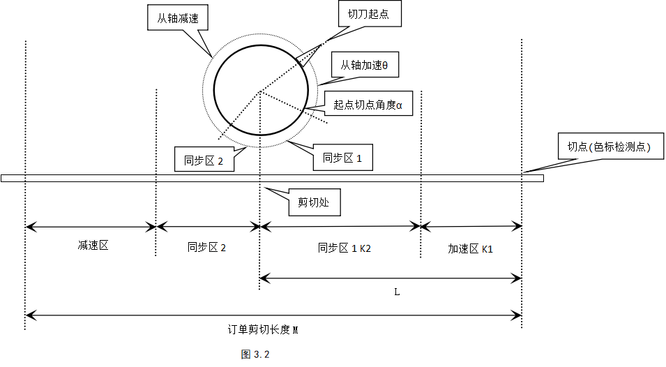
图24 figure 4.2 Flying scissors
Note: α is the angle from the starting point of the cutting blade to the cutting point vertically below, and the sum of synchronization zones 1 and 2 is β
Assuming the cutting length of the order is M, the distance L between the cutting point and the cutting point at the initial position of the axis, the acceleration zone angle θ, the synchronization zone angle β, the angle α between the starting point of the cutting blade and the cutting point, the cutting blade diameter D, and the number of cutting blades i
Equation ①: Spindle acceleration zone K1=M * θ/(360/i)
Equation 2: Spindle synchronization zone K2=(α - θ)/360) * π * D, (α>θ, the angle between the starting point and the cutting point of the cutter must be greater than the angle in the acceleration zone)
Equation ③: The distance from the starting point to the cutting point L=K1+K2
Equation ④: θ+β<(360/i), 0<α - θ<β
Among them, M, α, D, and i are all known parameters
If fixed length cutting is chosen, a reasonable angle θ, β can be determined within the range of ④ to ensure a smooth acceleration and deceleration process. Combining ①②③, L can be calculated to control the length of the first material.
If calibration cutting is selected, the color code is the cutting point, and L is the distance from the color code point to the cutting point, which can be adjusted. By determining a suitable angle θ and combining it with ①②③, L can be calculated. Combined with ④, the range of values for the synchronous zone angle β can be determined, and β or θ can be adjusted within this range to make the curve smooth. Of course, the punctuation mark can be offset according to the actual situation, thereby offsetting the cutting point.
In actual operation, if the cutting length of the order is much smaller than the circumference of the flying shear wheel, the acceleration and deceleration process of the rotary cutting shaft will be more intense. Conversely, the waiting distance after the rotary cutting shaft decelerates to zero will be longer.
Set an appropriate following coefficient based on the following situation. The larger the following coefficient, the tighter the following and the faster the response from the axis.
Write a manual program for running the master and slave axes, and write a manual program for resetting the axis to the origin.
After the setting is completed, a trial run can be conducted to observe the speed synchronization situation in the synchronization zone. If the difference is not significant, a trial cut can be made. If the difference is too large, it is necessary to check whether the parameter settings are normal to ensure the accuracy of each mechanical parameter. For example, due to the accuracy of the mechanical structure, there is a significant error in the forward distance of the master and slave axes per revolution, and whether there is a significant error in the diameter of the flying shear wheel including the cutting blade. If necessary, actual measurement needs to be carried out through a manual program, and the corrected value needs to be re entered before restarting the ECAM.
After trial cutting, there may be a situation where the cutting length does not match the set length. In this case, it is necessary to manually run the program to make the master and slave axes run a fixed number of turns. Then, based on the actual measured length, calculate the actual forward distance of each turn of the master and slave axes and re-enter it. For the flying shear, the actual circumference and diameter of the flying shear wheel can be calculated based on this.
After a certain number of trial runs, if there is a significant cumulative error in the fixed length shear, it is possible to consider setting a displacement compensation coefficient. In the direction of spindle motion, the tangent point lags behind (the length of the material and the length of the order), and the displacement compensation coefficient is greater than 1, otherwise it is less than 1. (It is recommended to start setting this value from a distance of less than 0.01 from 1)
1.6. Attention
After disabling the ECAM command, the modified parameters will only be updated when re enabled. Changing parameters during operation will not take effect.
Pay attention to setting parameters that are not reasonable (the parameter setting section introduces the range of parameter settings and various limiting relationships). After enabling, the PLC will report cam parameter errors and will not run. At this time, it is necessary to check whether the parameter settings are correct, change them correctly, and disable them again before continuing to run.
The synchronization zone flag can be used to trigger cutting, and the falling edge of the synchronization zone can be used for counting.
It is recommended that the acceleration and deceleration process be as smooth as possible, otherwise it may cause excessive vibration of the mechanical structure, which may affect the measurement of the encoder, and may also cause servo over limit alarm due to high shaft speed.
The reset of the flying shear is different from that of the follow-up shear. When resetting the flying shear, it is necessary to select the return path according to the current position of the cutting blade when returning to the starting point, and be careful not to touch the feeding shaft.
During operation, it is important not to clear or manually modify the target value register, as this may result in errors where the spindle pulse frequency exceeds the limit due to sudden changes in the spindle target value.
After the clutch marking position is set, the color code detection is invalid. Before resetting the clutch flag, it is necessary to ensure that all other pulse commands controlling the pulse port have been disabled.
If the memory spindle phase is set, the cam curve needs to be restarted from scratch. The ECAM can be disabled, all operating parameters cleared, and re enabled.
1.7. Actual case of flying scissors
Before using the electronic cam command, it is necessary to have a clear understanding of its working principle and a relatively clear understanding of the parameter types and ranges in each mode. When parameter configuration errors occur, refer to the comments in the previous paragraph to correct unreasonable parameters.
Case 1: toothpick machine cutting project
1.7.1. Project Background
Plastic packaging film slitting machine: Cut several toothpicks wrapped in long strips of plastic film, with a color mark between each toothpick. This project belongs to the standardized flying shear, so the port configuration, mechanical parameters, and flying shear parameters are determined according to the debugging steps.
1.7.2. Port configuration and determination of flying shear parameters
- Port configuration
The pulse output port and direction port Y0, Y4 of the rotary cutting shaft (from the shaft), due to the servo drive of the customer's spindle, the pulse port Y1, and the absence of an encoder on the spindle pressure roller, the target value register is D8142 (if there is an encoder, the target value register is the corresponding register of the high-speed counter).
Color code sensor X0, polarity normally open. There are two cutter origin sensors X4 on the rotary cutting shaft (with two detections within one circle), with normally open polarity. Before use, ensure that the sensor signals are valid. The clutch is set to M100 and is effectively engaged. After disability, it can remember the main axis phase.
- Mechanical parameters and flying shear parameters:
Mechanical parameters: The number of pulses per revolution of the main shaft is 10000pcs, the forward distance per revolution of the main shaft is 126mm, the number of pulses per revolution of the secondary shaft is 10000pcs, the diameter of the flying shear wheel is 60mm, the distance between the two color marks is 92mm, when the rotary cutting shaft detects the origin signal, the angle between the cutting blade and the cutting point is 108 °, and the number of cutting blades is 2. Require cutting points to be colored punctuation marks.
Flying shear parameters: The order cutting length is set to 90mm, the acceleration angle θ, the distance L between the color dot and the cutting point, and one cycle is 180 °
90 * θ / (360 / 2 ) + ( (108 - θ) / 360 ) * π * 60 = L => 0.0236 * θ = 56.549 - L
Due to the range of θ being between 0 ° and 108 °, for the sake of rationality, it can be reduced to between 30 ° and -70 °, and the corresponding L is calculated to be between 55.841-54.997mm. Assuming the acceleration angle θ=50 °, L=55.369 mm is obtained, and the synchronization zone β=90 ° is temporarily taken (ensuring that the synchronization zone angle is sufficient to complete the shearing)
The length of the order is equivalent to the arc length traveled by the flying shear in one cycle (half of the circumference), so the acceleration and deceleration process will be relatively smooth.
1.7.3. Create ladder diagrams related to rotary cutting axes
- Create a zero return instruction, as shown in Figure 6.1.

图25 Figure 6.1 Ladder Diagram Program
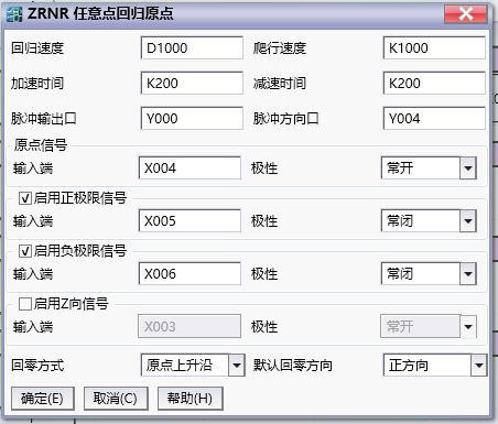
图26 Figure 6.2 Detailed Settings
Set the pulse output port and direction port of the electronic cam to Y0 and Y4 respectively, configure the port and polarity of the origin signal and positive and negative limit signals, select the zeroing method and direction, and determine the position of the zero point according to the zrnr instruction document.
Attention: It is best not to have any workpiece on the spindle when returning to zero, otherwise it is important to note that the return path should not touch the workpiece.
- Create a manual command as shown in Figure 6.3.

图27 Figure 6.3 Ladder Diagram Program
Create manual commands for Y0 and Y4 to manually move the electronic cam shaft. During the engagement of the ECAM clutch, these pulse commands can be used to control the rotary cutting shaft. Before the clutch fails, it must be ensured that these pulse commands are in the disengaged state.
Create ECAM commands in the ladder diagram and set various parameters of the flying shear.
Port settings:
Pulse output: Y0
Pulse direction: Y4
Target value address: D8142
Target value direction: increasing
Clutch marker: M100
Do you remember the main axis phase? Yes
Mechanical parameter settings::
Number of pulses per revolution of the spindle: 10000pls (the number of pulses emitted by one revolution of the spindle servo)
The forward distance of the spindle per revolution: 126mm (the actual distance traveled by the spindle after one revolution of servo rotation)
Number of pulses per revolution from the axis: 10000 pls (the number of pulses required for one revolution of the shearing servo motor)
Flying shear wheel diameter: 60mm
Flying shear parameters:
Order cutting length: 90mm (cutting material length)
Number of cutting blades: 2
Acceleration angle: 50 °
Synchronization angle: 90 °
Calibration settings:
Select calibration cutting: (cut after detecting the color code)
Color code marker: X0
Color protection distance: 0mm (color detection distance=order cutting length+color protection distance=90+0=90mm)
Compensation coefficient:
Spindle speed compensation coefficient: 0 (usually set to 0)
Spindle displacement compensation coefficient: 1 (For fixed length shear, it needs to be set according to actual operating conditions, with a range of 0.9-1.1. For fixed length shear, set 1 here.)
Spindle phase compensation: 0mm (set according to actual needs)
Current operating status:
The consecutive addresses starting from D6000 are used to display operational parameters.
The consecutive addresses starting from M7000 are used to display the running flag bit.
Follow coefficient:
Magnification factor from axis: 1
Reduction factor from axis: 1
Follow performance: 50 (the above parameters are generally assumed to be sufficient)
- Generated cam curve graph
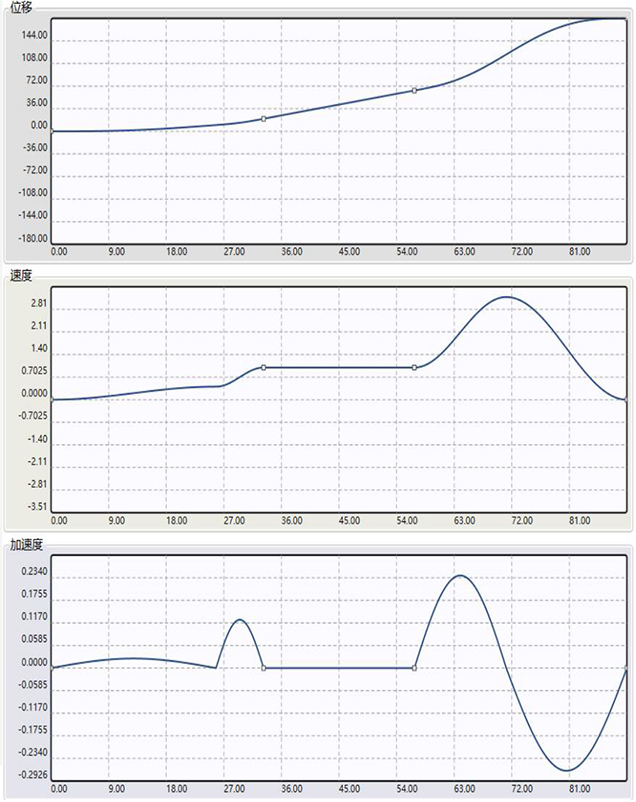
图28 Figure 6.4 Cam Curve Diagram
The schematic diagram of the flying shear curve shown in Figure 6.4: In the acceleration zone, the ratio of the rotary cutting shaft speed to the main shaft speed is less than 1, and the speed ratio in the deceleration zone is less than 3. The shaft speed is higher in the middle of the deceleration zone. In this example, the speed in the deceleration zone can be further reduced by adjusting the synchronization zone or acceleration zone. In practice, it may take multiple attempts to arrive at an overall stable value.
- Overview of ladder diagram logic
When powering on for the first time, first call the ZRNR command to return the flying shear table to zero.
After confirming that the spindle is in its initial position, connect the ECAM command for trial operation and cutting, observe the operating conditions, adjust mechanical parameters, etc.
During the operation of the ECAM command, turning on the clutch flag X1 can release the binding relationship between the master and slave axes. It is recommended to stop the spindle movement first and then set the clutch flag. After setting the clutch flag position, the chasing shear servo worktable or flying shear wheel can be moved through the JOG command. When the JOG command fails, the clutch flag position X1 can be reset. At this time, the master and slave shafts are re bound and continue to operate from the master and slave shaft positions at the clutch flag position. Note that there is no need to disable the ECAM command during the engagement of the clutch, otherwise the phase relationship between the master and slave axes will be cleared and the operation will start from scratch without memorizing the main shaft position.
Due to the selection of the memory spindle phase, re powering after a power outage will restart the operation from the position at the time of the power outage.