1. Arc Interpolation ARCI/ARCF
1. Arc Interpolation ARCI/ARCF
| Corresponding Command | Comments/Instructions | parameter |
|---|---|---|
| ARCI/ARCF | Arc interpolation instruction | Plane system number |
| line type | ||
| X-axis endpoint coordinates (K/D) | ||
| Y-axis endpoint coordinates (K/D) | ||
| Relative/Absolute Coordinates | ||
| Acceleration time (K/D) | ||
| Deceleration time (K/D) | ||
| Speed (K/D) | ||
| Arc type (two-point, three-point, center) | ||
| Two points: radius (K/D), three points: midpoint X/Y coordinates (K/D), center: center point X/Y coordinates (K/D) | ||
| Arc direction (clockwise/counterclockwise) | ||
| superior/minor arc |
1.1. Instruction Description
- The PLC high-speed pulse output port is Y0~Y1 or Y0~Y3, with a pulse frequency range of 0~200KHz;
ARCI/ARCF are integer parameter instructions and floating-point parameter instructions, respectively, corresponding to pulse pls and millimeter mm units;
The function of this instruction is to run the set parameter arc from the current position to the endpoint position in the specified plane system;
It is legal for the running length and acceleration/deceleration time to satisfy the following relationship (in practical applications, try to satisfy this relationship as much as possible, otherwise the program will automatically adjust the speed):
0. 5 x (acceleration time, deceleration time) x speed&# 60= Arc length
When the parameters set by the user are very unreasonable, the interpolation instruction will stop pulse output when an error is detected and provide an error code in the D8176 register. The user can troubleshoot the error based on the error code. When the parameters set by the user are adjustable and unreasonable, the program will automatically correct the parameters.
When setting parameters in two-point arc mode, it should be noted that the distance between the current point and the target point should be less than the diameter of the straight line. If this condition is not met, the distance of the straight line should be used as the diameter to re plan the arc path;
When setting parameters in three-point arc mode, it should be noted that the current point, midpoint, and target point cannot be on the same straight line;
When setting parameters in the arc drawing mode, it should be noted that the center coordinates must be on the perpendicular bisector of the starting and ending lines, and cannot be arbitrarily set.
When the radius of the arc is small and the speed is high, if it meets the requirements of acceleration and deceleration legality, it is also necessary to consider whether it will cause excessive bow height errors. The relationship between speed, radius, and bow height errors is shown in the figure. When the radius of the arc is small and the speed is high, it is easy to cause significant bow height errors. If the bow height error is too large, the system will slow down (small circle speed regulation characteristic). In actual use, do not use arcs with a radius that is too small.
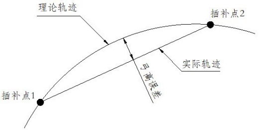
图1 Bow height error
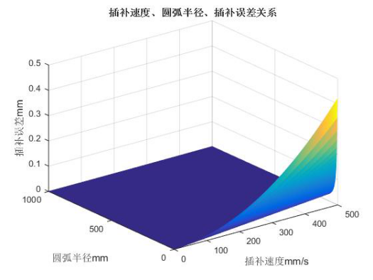
图2 Speed, radius, bow height error relationship diagram
1.1.1. Instruction usage instructions
1) Firstly, select the plane number. For plane settings, please refer to "Plane System Settings". If the plane system is not enabled, it will not function properly;
2) The instruction unit can be in millimeters (mm) or pulses (pls), corresponding to the ARCF and ARCI instructions, respectively. It is recommended that users use millimeters as the unit, and the parameters are in line with reality, without the need for conversion, making it less prone to errors;
3) The X-axis endpoint coordinates and Y-axis endpoint coordinates are the endpoint positions of the arc operation, which can be input with data type K/D. When using the D register to input parameters, the endpoint coordinates are assigned to the D register using MOVD or MOVF instructions, depending on whether the interpolation instruction is ARCI or ARCF type;
4) Relative/absolute coordinates. If selected as relative coordinates, the endpoint coordinates set will be the offset based on the current point. If it is an absolute coordinate, the endpoint coordinate represents the absolute position relative to the origin of the world coordinate system, as shown in the relative/absolute diagram of the line command;
5) Acceleration time and deceleration time can be directly set as a constant K or as a D register. When initializing the instruction, the value in the D register is read once as the acceleration and deceleration time. The acceleration and deceleration time can only be assigned using MOV, which is a 16 bit integer in milliseconds. Due to the interpolation cycle of the algorithm, if the acceleration and deceleration time is too short and the pulse frequency jumps too much, it cannot achieve the acceleration and deceleration effect. Interpolation acceleration and deceleration are asymmetric S-shaped acceleration and deceleration, and the acceleration and deceleration segments are controlled by acceleration and deceleration time, referring to the asymmetric S-shaped acceleration and deceleration diagram of the straight line command.
6) The speed represents the composite speed of XY axis, and the speed parameter can be set to K or D. If it is set to constant K, the linear speed is not adjustable. If it is set to D register, when the value of D register changes, the speed will also change accordingly, which can realize real-time speed regulation. During acceleration and deceleration, adjust the speed parameter, and the speed change will be adjusted immediately after the acceleration and deceleration. However, it should be noted that whether to use MOVD or MOVF for assigning speed to the D register depends on whether the interpolation instruction type is ARCI or ARCF. When the unit is set to pulse pls, the speed unit is pls/s, and MOVD is used to assign the speed. Conversely, MOVF is used. If the X-axis and Y-axis pulse equivalents set by the planar system are not equal, the true velocity is calculated based on the X-axis pulse equivalent by default. When the acceleration, deceleration, and speed parameters do not meet the above legal relationship, the system will automatically reduce the speed parameters to make them legal, referring to the illegal S-shaped adjustment chart of the straight line command.
7) The types of arcs are divided into two-point arc drawing, three-point arc drawing, and center arc drawing. The parameters that need to be set for the two are different. When selecting two-point arc drawing, as shown in the schematic diagram of two-point circle drawing, there are four arc paths for determining the radius from the current point to the target point. According to the clockwise order and the quality of the arc, a unique arc path can be determined. When choosing to draw an arc with three points, simply add the coordinates of the midpoint. The three points determine the unique arc, but they should not be on the same straight line. When selecting the center to draw an arc, knowing the center, starting point, ending point, and clockwise or counterclockwise direction can uniquely determine a single arc.
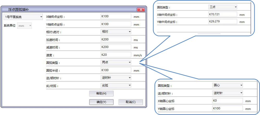
图3 ARCF instruction diagram, draw a 1/4 arc with a radius of 100mm
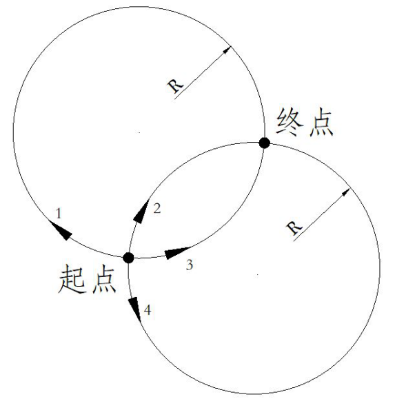
图4 Two point circle diagram
| Register Pulse | Output Port |
|---|---|
| M8134 | Y000 |
| M8135 | Y001 |
| M8136 | Y002 |
| M8137 | Y003 |
| Register Pulse | Output Port |
|---|---|
| M8138 | Y004 |
| M8139 | Y005 |
| M8140 | Y006 |
| M8141 | Y007 |
| M8142 | Y010 |
| M8143 | Y011 |
| Register Pulse | Output Port |
|---|---|
| M8144 | Y000 |
| M8145 | Y001 |
| M8146 | Y002 |
| M8147 | Y003 |
| Register Pulse | Output Port |
|---|---|
| D8140(D8141) | Y000 |
| D8142(D8143) | Y001 |
| D8144(D8145) | Y002 |
| D8146(D8147) | Y003 |
| Register Pulse | Output Port |
|---|---|
| D8148(D8149) | Y004 |
| D8150(D8151) | Y005 |
| D8152(D8153) | Y006 |
| D8154(D8155) | Y007 |
| D8156(D8157) | Y010 |
| D8158(D8159) | Y011 |
1.1.2. Attention:
For high-speed pulse output, it is designed for external high-speed devices. To count the pulses, only the high-speed pulse input counter can be used, and internal counters or Y edge changes cannot be used for counting. When used as a high-speed output, it cannot be used as a regular output port;
The OFF time of transistors has the characteristic of being prolonged under light loads. So, when responsiveness is required, please design a load resistor to increase the load current when the load is lighter;
The pulse accumulation count registers (D8140~D8158) are important registers that can be read and written. When a new value is written, the count will be added or subtracted based on the new value;
Due to the directional output of the pulse in this instruction, the pulse accumulation count registers (D8140~D8158) count according to the direction;
When outputting high-speed pulses, the values in the pulse accumulation count registers (D8140~D8158) are discontinuous and constantly changing. When used for judgment, please use size comparison instead of equal judgment;
- Do not set the acceleration and deceleration time too small, otherwise there will be no acceleration and deceleration effect;
When the unit is set to pulse pls, the speed unit is pls/s. If the X-axis and Y-axis pulse equivalents set by the planar system are not equal, the true speed is calculated by default based on the X-axis pulse equivalent;
- The pulse is sending a flag bit. For example, M8134 only represents whether Y0 is outputting a pulse. If it is necessary to detect whether a pulse is being sent in plane system 1, use M8144. When running the interpolation command, if any axis in the plane system sends a pulse, this bit will be ON;
When drawing an arc between two points, the distance between the current point and the target point in a straight line should be less than the diameter;
When drawing an arc at three points, do not align the three points in a straight line;
When drawing an arc on the center of a circle, the center must be on the perpendicular bisector of the starting and ending points;
- The current point coordinates should not coincide with the target point coordinates;
When the pulse command is used to output port Y, the Y port cannot be used for other purposes, that is, ordinary commands cannot perform ON or OFF operations on the Y port anymore.
If the frequency of multiple pulse pulses exceeds 200K, a pull-up resistor needs to be added to the pulse output port to ensure that the pulse waveform is not distorted. The pull-up voltage is 24V, and the recommended pull-up resistor is 1K.
1.2. The valid operands of the instruction
1.2.1. Integer Instruction (ARCI)
| Input/Output | Data Type | operand | Description |
|---|---|---|---|
| ID | 16 bit unsigned integer | K/H | Number |
1.2.2. Float instruction(ARCF)
| Input/Output | Data Type | operand | Description |
|---|---|---|---|
| ID | 16 bit unsigned integer | K/H | Number |
1.3. Example
From the current position, move to the endpoint of (100mm, 100mm) with a radius of 100mm, counterclockwise, with a bad arc. M20 is set to start the arc, M500 is set at the beginning of the "arc motion", and M500 is reset after the end. Set the X-axis to Y0 and Y-axis to Y1 for the planar system, and the ladder diagram is shown below.
command table:
NETWORK 000
LD M20
ARCF K1
NETWORK 001
LD M8144
MPS
MEP
SET M500 K1
MPP
MEF
RST M500 K1
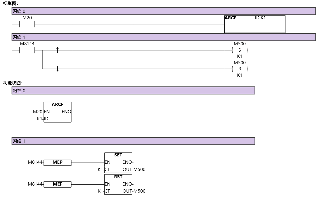
图5 ARCI