1. TECAM guide
1. TECAM guide
1.1. preface
Applicable models:
Please check with our enginner or sales, for this function.
Basic knowledge about electronic camshafts can be found in the ECAM instruction;
This instruction consists of two parts: TECAM-DATSET and TECAM. TECAM-DATSET is an electronic cam table used to set the mechanical parameters of the master and slave axes and the basic parameters of the cam, and generate cam curves. Currently, up to two tables can be set, but dynamic modifications are supported during operation (effective for the next cam cycle); TECAM is an electronic cam command used to set operating parameters. Electronic cam commands can be used multiple times, but it is important to ensure that the operating addresses are not the same;
The spindle can choose high-speed pulse/high-speed counting/D register virtual axis, and the slave axis is only limited by the number of pulse ports of the PLC (but the mode 64MT-AC can provide correction signals for 10 slave axes, while other models can only provide up to 3).
The advantage of using a cam table for electronic camshafts is that the parameters are set and calculated first, and then TECAM instructions are directly executed instead of running while running. This method reduces the system resources occupied and improves operational efficiency by directly checking the table without waiting for the running results. Compared with ECAM instructions, it has higher following stiffness, richer functions, and more convenient use, but does not support cam curves with discontinuous speed at spindle reversal and key point connections.
1.2. TECAM-DATASET instruction description
TECAM-DATSET has four modes, namely flying shear, chase shear, universal cam (key point), and universal cam (insertion point). When calling this command for the first time, the mode needs to be selected, and the parameters set in different modes are different, which need to be set according to the actual situation. The meanings of each address in TECAM-DATA SET are shown in the following table:
1.2.1. The first address of the data parameter is D, and the rest of the addresses are added with the first address in sequence
| Offset Address | Description | Data Type | Data Range | Description |
|---|---|---|---|---|
| 0 | Data creation method/data modification starting point index for electronic cam table (intermediate point mode and key point mode) | int | 0-9999/10000 \ -10049/10050/0051 | 0-9999 is the input for intermediate interpolation points, 10000-10049 is the input for key points, 10050 is the flying shear, 10051 is the chasing shear |
| 2 | Data Depth | int | 0-2048/0-50 | The maximum value for intermediate interpolation points is 2048, and the maximum value for key point input is 50. The sum of data modification and index should not exceed the above values, and it is invalid in the data input mode of chasing flying shear |
| 4 | Spindle magnification | float | Spindle scaling factor, only in key mode, default to 1 | |
| 6 | From axis magnification | float | From axis scaling coefficient, only in key mode, default to 1 | |
| 8 | Data unit | int | 0,1,2 | Both key points and chase shear mode are applicable; 0:pls, 1:mm; Only the position parameters are calculated in PLS units, and the equivalent calculation of speed ratio is still based on the distance per turn and the number of pulses per turn (different from the PLS unit mode for key points, which calculates directly based on the set slope and pulses, without considering pulse equivalent) |
| 10 | Distance traveled by the spindle per revolution | float | Distance traveled by the spindle motor per revolution | |
| 12 | Number of pulses per revolution of spindle | int | Number of pulses required for one revolution of spindle motor | |
| 14 | Distance traveled per revolution from the shaft (diameter of the flying shear wheel when flying shear) | float | Distance traveled by rotating one revolution from the shaft motor: the lead of the lead screw may be used for follow-up shear, and the diameter of the flying shear wheel is used for flying shear; Note: The upper interface of the flying shear shows the distance moved per revolution from the axis. When generating the subroutine, it will be automatically divided by π. When manually rewriting the subroutine, please note that the value to be filled in the subroutine is the diameter of the flying shear wheel | |
| 16 | Number of pulses per revolution from the shaft | int | Number of pulses required to complete one revolution from the shaft; Note: This is the number of pulses required to be emitted by the PLC. If there is a deceleration structure, the reduction ratio should be multiplied by the number of servo single turn pulses | |
| 18 | Rated shaft speed | int | 0: FGm-64MT-AC defaults to 490kHz, while others default to 190kHz; Intermediate or interpolation point input (in Hz), follow-up or flying shear input (in r/min) | |
| 20-28 | Reserved | |||
| 30 | Electronic cam data creation error | int | 1: Cam table data creation method and data depth error, 2: incorrect distance or pulse count per turn, 3: incorrect number of cutting blades, 4: illegal cutting angle, 5: synchronization area exceeds the total cutting length, 6: the rated speed of the shaft exceeds the limit, 7: abnormal length settings in each area, 8: insufficient cutting total length, 9: synchronization area exceeds the screw stroke, 10: spindle data inversion or stagnation, 11: data index or depth error, 12: electronic cam table is currently occupied | |
| 32 | Rated pulse frequency of the shaft | int | Read only | Calculated from the rated speed, in Hz |
| 34 | Theoretical maximum speed limit of the main shaft | int | Read only | Calculated based on the rated frequency of the secondary shaft and the maximum master-slave shaft speed ratio, in Hz, only effective for the chasing shear |
| 36 | master-slave axis synchronization area magnification | float | read-only | obtained from spindle pulse equivalent/slave axis pulse equivalent, only effective for chasing flying shear |
| 38 | Maximum master-slave axis speed ratio | float | read-only | Calculate the maximum master-slave axis speed ratio based on the curve, only effective for chasing flying shear |
| 40 | Number of spindle cycle pulses (pls) | int | Read only | Used to convert spindle length units in mm units to pls for reading, only valid for flying shear |
| 42 | Knife offset distance | float | Flying shear is the phase of the midpoint of the synchronization zone, and chasing shear is the phase of the starting point of the synchronization zone |
1.2.2. The first address of data storage is D, and the rest of the addresses are added with the first address in sequence
The data storage lengths occupied by flying shears, chasing shears, universal cams (key points), and universal cams (insertion points) are different. The specific number of registers occupied and the meaning of each register are explained below.
1.2.2.1. Flying shear input
| Offset Address | Description | Data Type | Data Range | Description |
|---|---|---|---|---|
| 0 | Spindle cutting length | float | Cutting length | |
| 2 | Synchronization zone angle | float | unit °, from axis synchronization zone length | |
| 4 | Number of cutting blades | int | Number of cutting blades: one spindle cycle corresponds to several slave cycles, default is 1 | |
| 6 | Acceleration curve selection | short | 0: Constant acceleration (quadratic curve) 1: Trivariate curve 2: Double segment oblique cosine curve | |
| 7 | Electronic cam curve selection | short | Not yet open | |
| 8 | Starting angle of synchronization area | float | The sum of the starting angle of the axis synchronization area and the angle of the synchronization area should be less than the total length of the axis; Constant acceleration is ineffective | |
| 10 | Starting point of spindle synchronization zone | float | Starting point of spindle synchronization zone (only applicable for cubic curves), the sum of distances from the synchronization zone should be less than the total length of the spindle; Constant acceleration is ineffective | |
| 12 | Origin speed ratio | float | Slope at the beginning and end of the cam curve |
In constant acceleration mode, the synchronization zone is located in the middle of the entire journey, and the size of the speed adjustment zones on both sides corresponds, which is automatically calculated;
Acceleration curves 1 and 2 need to be controlled by the starting angle of the synchronization zone/the starting point of the main axis synchronization zone/the speed ratio at the origin to control the linearity. Currently, the upper level can directly display cubic curves;
Number of cutting blades: If 2 is filled in, the original one from the axis cycle has been split into two cycles. If the original cycle rotates once, after splitting, it will rotate half a cycle.
Parameter setting requirement:
Starting angle from axis synchronization zone+synchronization zone angle<(360 °/number of cutting blades)
Starting point of spindle synchronization zone+synchronization zone length< cutting length
1.2.2.2. Chase cut input
| Offset Address | Description | Data Type | Data Range | Description |
|---|---|---|---|---|
| 0 | Spindle cutting length | float | Cutting length | |
| 2 | Length of spindle acceleration zone | float | ||
| 4 | Spindle synchronization area length | float | ||
| 6 | Length of spindle deceleration zone | float | ||
| 8 | Length of spindle reversing area | float | ||
| 10 | Length of waiting area behind the spindle | float | Waiting distance at the end of the follow-up cutting | |
| 12 | Maximum travel from axis | float | Maximum distance that can be moved from the axis | |
| 14 | Cutting Time | int | Time ms used for cutting from the axis (not yet enabled) | |
| 16 | Length of waiting area in front of the spindle | float | Waiting distance for starting the follow-up cutting |
Parameter setting requirement:
Main spindle waiting area+acceleration area+synchronization area+deceleration area+reversing area+rear waiting area< main spindle cutting length,Because there is a return area, which is the difference between the left and right sides of the inequality.
hasing shear from axis acceleration distance+synchronization zone+deceleration zone< Chasing shear from axis limit distance,To ensure that the secondary axis does not exceed the limit and to protect the secondary axis; When the set parameters do not meet this condition, the distance between the acceleration zone and deceleration zone will be automatically adjusted to make the total length less than the limit stroke of the shaft; If the synchronization zone distance has exceeded the limit distance, the cam curve generation fails, and the offset address D30 will report an error message.
1.2.2.3. Universal cam (key point)
| Point number | offset address | main axis coordinate | sub axis coordinate | slope (speed ratio) | line type | resolution |
|---|---|---|---|---|---|---|
| 0 | 0 | 0 | 0 | 0 | 0 | |
| 1 | 10 | |||||
| 2 | 20 | |||||
| 3 | 30 | |||||
| ... | ... | |||||
| 49 | ... |
♦ The first key point is that only the speed ratio is valid, the rest are 0, and the data depth must be≥ 2
♦ Each key point contains the main axis coordinates, including the axis coordinates, slope of the point, line type from the point to the previous point, and resolution from the point to the previous point, occupying a total of 10 double word registers
♦ Line types include straight lines, quadratic curves, cubic curves, and double segment oblique cosine curves (corresponding to 0 1 2 3)
♦ Maximum data depth of 50
♦ The sum of resolutions shall not exceed 2048
♦ Only cam curves with continuous speed ratios can be generated (i.e. each point can only have one slope), and when the starting and ending slopes are different, there will be a sudden change in speed at the end of the cycle
1.2.2.4. Universal cam (insertion point)
| Point number | offset address | main axis coordinate | sub axis coordinate |
|---|---|---|---|
| 0 | 0 | 0 | 0 |
| 1 | 4 | ||
| 2 | 8 | ||
| 3 | 12 | ||
| ... | ... | ||
| 2047 | ... |
♦ The first point must be (0,0), and the data depth must be>=2
♦ Each insertion point contains the main axis coordinate and the sub axis coordinate (pulse number), occupying 2 double word registers
♦ The maximum data depth is 2048
1.2.3. Write data to the first address of the flagM
| Offset Address | Description |
|---|---|
| 0 | Electronic cam gauge refresh flag |
| 1 | Electronic cam gauge writing success flag |
The rising edge of the flag bit (first address M+0) is valid, and if the write is successful, the write success flag bit (first address M+1) is set to ON.
When TECAM-DATA SET is enabled, M0 is not set and needs to be manually set. It can also be triggered by taking a rising edge.
When TECAM-DATA SET is disabled, both of these flag bits will be reset.
When modifying the cam curve, it is necessary to provide the rising edge of the refresh flag before starting to calculate the new curve. After the calculation is completed, the successful write flag will be set to ON.
1.3. TECAM Instruction description
The TECAM instruction directly runs the data calculated in TECAM-DATA SET, and the operating parameters need to be run in TECAM. For example, determining the main axis and the following sub axis is determined in this instruction, and determining whether it is fixed length or calibrated cutting is also set in the operating parameters of this instruction.
1.3.1. Run the parameter with the first address D, and add the first address to the remaining addresses in sequence
| Offset Address | Description | Data Type | Register Type | Data Range | Description |
|---|---|---|---|---|---|
| 0 | Electronic cam table serial number | int | D | 0,1 | Currently, only 0 and 1 can be filled in |
| 2 | Cam error status | int | D | Read only. Cam error status prompt, note that there may be multiple errors at the same time, and the error code is a sum value; 0x00000001 (electronic cam command, specified cam table number does not exist); 0x00000002 (electronic cam command, specified spindle source does not exist); 0x00000004 (electronic cam command, spindle index number illegal); 0x00000008 (electronic cam command, correction signal not present); 0x00000010 (electronic cam command, start signal not present); 0x00000020 (electronic cam command, start signal index does not exist); 0x00000040 (electronic cam command, corresponding electronic cam table not initialized); 0x00000080 (electronic cam command, illegal limit for flying car pulse); 0x00000100 (electronic cam command, phase adjustment value not set); 0x00000200 (electronic cam command, phase adjustment times not set); 0x00000400 (electronic cam command, correction signal compensation ratio abnormal); 0x00000800 (electronic cam command, the number of operating cycles is not determined when there is a start signal); 0x000001000 (electronic cam command, single cycle correction signal trigger frequency not set); 0x000002000 (electronic cam command, exceeding the limit of the flying car); 0x000004000 (abnormal sudden change in spindle phase); 0x000008000 (abnormal triggering of start signal); 0x00010000 (abnormal triggered by correction signal); 0x00020000 (accumulated correction distance too long); 0x00040000 (there is reverse data on the spindle); 0x00080000 (invalid directional port); 0x00100000 (abnormal correction count); 0x00200000 (failed to query master/slave axis position); 0x00400000 (Key point interval positioning timeout) | |
| 4 | Accumulated pulse count of spindle | int | D | Read only. The accumulated phase from the start of the spindle to its operation, including the effective spindle phase adjustment, cycle jump, correction adjustment, and speed compensation, will be included | |
| 6 | Current phase of spindle | int | D | Read only. The current theoretical position of the spindle in the cam table will restart counting after one revolution (refreshed every calculation cycle, currently brushed once every 1ms) | |
| 8 | Accumulate pulse count from axis | int | D | Read only. Accumulate the number of pulses taken after starting the axis, return to zero after returning to the origin | |
| 10 | Read only from the current phase of the axis | int | D | . Starting from the current position of the axis, counting will resume upon returning | |
| 12 | Accumulate pulses from axis theory target | int | D | Read only. Consistent with the cumulative number of pulses from the axis | |
| 14 | Current spindle speed | int | D | Read only. The running speed after the spindle is turned on remains constant if it is a constant speed. Unit Hz | |
| 16 | Theoretical maximum speed of spindle | int | D | Read only. Corresponding electronic cam gauge | |
| 18 | Read only from axis current speed | int | D | . Different zones correspond to different speeds, and the speed of the slave axis and the current speed of the main axis should be consistent within the synchronization zone. Unit Hz | |
| 20 | Rated frequency from axis | int | D | Read only. Corresponding electronic cam gauge | |
| 22 | Send the current pulse value from the axis | int | D | read-only. Dividing by the calculation period (0.01s) is the current frequency of the slave axis | |
| 24 | Read only from the current paragraph number | int | D | on the axis. Follow up cutting: 1. Front waiting area 2. Acceleration area 3. Synchronization area 4. Deceleration area 5. Reversing area 6. Return area (uniform acceleration section) 7. Return area (uniform deceleration section) 8. Rear waiting area; Flying shears: long materials (1. waiting zone 2. acceleration zone 3. synchronization zone 4. deceleration zone), short materials (1. deceleration zone 2. synchronization zone 3. acceleration zone); Key point mode: counting by key point paragraphs; Middle point mode: Invalid. When the length of a certain area is 0, the sequence of paragraph numbers behind it moves forward. | |
| 26 | Total number of operating cycles | int | D | Read only. Count once from the beginning of the cycle when entering the axis, the total number of cycles that have been run | |
| 28 | Correction compensation total | int | D | Read only. The number of spindle offset pulses at the correction signal is the theoretical value for speed compensation, which is the spindle frequency multiplied by 0.01. The deviation from this value is the number of mechanical correction pulses | |
| 30 | Speed compensation | int | D | Read only. The number of adjustment pulses for the spindle phase by speed compensation is theoretically calculated as the calculation cycle (currently 1ms) multiplied by the spindle frequency multiplied by 2 | |
| 32 | Number of spindle cycle pulses | int | D | Read only. Phase at the end of the spindle cycle (pls) | |
| 34 | Number of axial cycle pulses | int | D | Read only. Phase from the end of the axis period (pls) | |
| 36 | Spindle position display | int | D | Read only. Spindle phase display (refreshed every scanning cycle, but not involved in cam calculation) | |
| 38 | Spindle initialization position | int | D | Read only. When the cam is first engaged, the first sampled value of the spindle will be written to this address | |
| 40-46 | Reserved | ||||
| 48 | Spindle Type | int | D | 1,2,3 | 0: Invalid, 1: Actual Spindle Y, 2: High Speed Counter CV, 3: Virtual Spindle Vy (D0-D7999) |
| 50 | Spindle Position Index | int | D | When D48 is 1, the D50 range is 0-3 (corresponding to Y0-Y3), when D48 is 2, the D50 range is 0-20 (corresponding to CV235-CV254), and when D48 is 3, the D50 range is 0-7998 (corresponding to D0-D7999) | |
| 52-70 | Reserved | ||||
| 72 | Compensation signal | int | D | 0,1,2 | 1: Compensation signal X6, 2: Compensation signal X0, 3: Compensation signal X1 is used for axis correction and cannot be used for other external interrupt functions or high-speed counting related functions after being enabled |
| 74 | Cam start signal | int | D | 0,1,2 | 0: none (fixed length shear); 1:M; 2: X (When the calibration cutting start signal changes: the calibration cutting will switch to fixed length after executing the set number of cycles, and the fixed length cutting will switch to calibration in the next cycle) |
| 76 | Cam start signal address | int | D | Start address (decimal, for example, 0 represents M0/X0, 9 represents M9/X11, which is determined by the type of start signal), X is the corresponding PLC input point range, and M is 0-7999 | |
| 78 | Number of triggers for single cycle correction signal | int | D | Number of triggers for compensation signal in a single cycle of the spindle, usually 1 for flying shear and 2 for chasing shear | |
| 80 | Cam table query input | int | D | >0 | Input master/slave shaft phase, enable the cam table query signal (offset address M10), and the corresponding slave/spindle position will be obtained from the cam table query slave shaft output (offset address D82). Note: When querying the spindle from the slave shaft, only monotonic cam curves are applicable |
| 82 | Cam table query output | int | D | Read only | See D80 |
| 84 | Position corresponding to correction signal | int | D | >0 | The main axis phase corresponding to the correction position is defaulted to 0, and the initial trigger position of the correction signal is used as the correction reference position. Otherwise, the offset position D84 (pls) is used as the correction reference position |
| 86-96 | Reserved | ||||
| 98 | Number of cam execution cycles | int | D | 0: Periodic cycle execution,>0: Non periodic execution times, only valid when there is a start signal, supports dynamic changes | |
| 100 | Cam Speed Limit | int | D | 0: There will be an error prompt but it does not affect the operation. The default is 1950, and multiplying by 100 is the upper limit of the shaft pulse frequency to prevent excessive speed | |
| 102 | Spindle adjustment phase | int | D | (- Spindle cutting length/2, Spindle cutting length/2) After setting, the enable needs to be used in conjunction with the (M+4) phase adjustment enable flag in the table below | |
| 104 | Spindle phase adjustment steps | int | D | >=2 | Used together with the spindle phase adjustment function, the smaller the adjustment speed, the faster it is; It is also the number of correction steps, the smaller the correction signal, the faster the phase adjustment after triggering the correction signal |
| 106 | Proportional coefficient of correction signal | float | F | It is only useful when the correction signal is turned on. For correction signals from the axis, the larger the correction amplitude, the more obvious the correction amplitude. It is recommended to set a value slightly greater than 1, and then increase or decrease it according to the fluctuation amplitude of offset address 28 | |
| 108 | Spindle phase sampling magnification | float | F | >0 | The default sampling magnification is 1. After filling in the value, the spindle phase used will be multiplied by this magnification as the new phase, which can be used to fine tune the cutting length and the synchronous speed ratio of the master and slave axes. |
| 110 | Speed compensation coefficient | float | F | >=0 | When following the spindle from the axis, there will be a lag of 2 calculation cycles, and the lag is proportional to the operating speed. When the spindle speed remains stable, it can be eliminated by adjusting the spindle phase. When the operating speed changes, it needs to be adjusted in real time according to the current spindle speed. This coefficient is used to adjust the amplitude of speed compensation. The default value is 0. In cases where speed compensation is required, write 1 first, and then observe that when the measurement increases the spindle speed, the synchronization zone changes from the axis position state. If it leads, slightly reduce the compensation coefficient, and if it lags, slightly increase it. |
| 112-126 | Reserved |
1.3.2. The first address of the status flag is M, and the rest of the addresses are added with the first address in sequence
| Offset Address | Description | Explanation |
|---|---|---|
| 0 | Electronic cam alarm flag | Read only. Electronic cam operation error flag, 0: no error, 1: error reported |
| 1 | Electronic cam initialization completed | Read only. 0: Not completed, 1: Completed |
| 2 | Master slave axis engagement mark | Read only. 0: Not completed, 1: Completed |
| 3 | End of cycle flag | Read only. The calibration process is initialized to 1, and after detecting the color code, 0 is placed. After sending the set number of cycles, 1 is placed; The fixed length process is initialized to 0, and when disabled, it stops and is followed by 1 |
| 4 | Phase adjustment enable flag | Write only. It needs to be manually triggered each time, 0: not enabled, 1: enabled. The spindle phase can be modified online, and the adjusted phase value depends on the (operating parameter first address D+102) spindle adjustment phase in the table above |
| 5 | Electronic cam stop mode indicator | Write only. 0: Stop immediately, stop immediately from the axis, 1: Stop at the end of the cycle, stop after returning to the waiting area from the axis |
| 6 | Will the data be retained after disabling | Write only. 0: Do not keep, run parameters cleared, 1: Keep data, run parameters keep current number |
| 7 | Cycle jump flag | The jump can only be made when the speed and phase are limited to 0. The main axis phase will directly jump to the beginning of the next cycle and enter the next cycle directly |
| 8 | Correction initialization signal | Rising edge trigger, can re read the reference position after correction abnormality trigger |
| 9 | Error code clearing signal | Rising edge trigger, can clear historical alarm error codes, refresh error code status |
| 10 | Cam table query signal (master slave) | In the enabled state, the slave phase (offset address D82) of the corresponding cam table will be calculated from the input of the spindle phase (offset address D80), and automatically reset after the calculation is completed |
| 11 | Reverse from axis prohibited | Can only be used for flying shear or key and midpoint modes without axis reversal; Do not reverse from the axis after enabling; When triggering correction/speed changes in a disabled state, there may be a reversal from the axis; |
| 12 | Cam table query signal (slave master) | In the enabled state, the main shaft phase (offset address D82) corresponding to the cam table will be calculated from the input of the slave shaft phase (offset address D80), and automatically reset after the calculation is completed; For inputs corresponding to multiple spindle positions, take the first position |
| 13 | Clutch Function | After enabling, the engagement between the master and slave shafts is disconnected, and the change in the main shaft no longer causes a phase change between the master and slave shafts. After disabling, it continues to operate from its original state |
| 14-31 | Reserved | Read Only |
1.4. Example
1.4.1. Example of fixed length cutting
1.4.1.1. TECAM-DATASET setting
The Order number can be selected as 0 or 1, indicating the first or second cam table. For example, fill in 0, and TECAM can call the data in the cam table thereafter,
Initial address of data parameter: Fill in a D register, for example fill in D100. This data will occupy a total of 40 registers from D to D+39
First address of data storage: Fill in an unused D register, for example fill in D200, and for details on the number of registers occupied, please refer to section 1.2
Data write flag: Fill in one M, for example fill in M100, occupying two M registers
**Main spindle movement distance per revolution: * * 100, ignoring all intermediate transmission mechanisms. The actual distance traveled by the machine after one revolution of the main spindle
**The number of pulses per revolution of the spindle is * * 800, which is determined based on the subdivision of the motor or the electronic gear ratio of the servo. It is best to set it to an even number or a multiple of 1000
**Moving distance per revolution from the shaft: * * 100, ignoring all transmission mechanisms in the middle, the actual distance traveled by the machine for one revolution from the shaft
**From the number of pulses per revolution of the shaft: * * 800, based on the subdivision of the motor or the electronic gear ratio of the servo, it is best to set it to an even number or a multiple of 1000
**From the rated speed of the shaft: * * default 0 is calculated based on the maximum pulse frequency of 190kHz; If it is a flying cutter, it can also be set to 2000, with a default unit of r/min

图1 Parameter setting for fixed length cutting
**Spindle cutting length (mm): * * 1000, float type, the length traveled by the spindle during the entire cutting process (from shaft start to shaft return waiting)
**Length of spindle acceleration zone (mm): * * 100, float type, the distance traveled by the spindle when accelerating from 0 to the same speed as the spindle
**Spindle synchronization zone length (mm): * * 160, float type, the distance traveled by the spindle within the same speed as the spindle
**Spindle deceleration zone length (mm): * * 100, float type, the distance traveled by the spindle when decelerating from the same speed as the spindle to 0
**Length of spindle reversing area (mm): * * 100, float type, distance traveled by the spindle from deceleration to 0 to restart in reverse direction
**Length of spindle waiting area (mm): * * 10, float type, the distance traveled by the spindle from the speed of the spindle returning to 0 to the start of the next cycle
**Maximum travel of the lead screw (mm): * * 780, float type, maximum travel that the lead screw can take during the shearing process, used for the protection of the lead screw
**Spindle return area length (mm): * * (530), float type, spindle return area length=spindle shear length \ - spindle acceleration area length \ - spindle synchronization area length \ - spindle deceleration area length \ - spindle reversing area length \ - spindle waiting area length, the return area has two sections, one is uniform acceleration and the other is uniform deceleration; If you need to quickly return from the axis, simply increase the length of the waiting area.
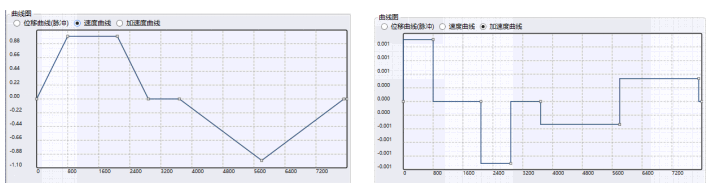
图2 Speed and acceleration curves
There are three curve graphs, displacement curve, velocity curve, and acceleration curve, which are divided into acceleration zone, synchronization zone, deceleration zone, reversing zone, return zone (2 segments), and waiting zone.
Click to create subroutine. After the subroutine is successfully created, if you need to modify the original parameters, you need to create it again. The second creation will overwrite the new data
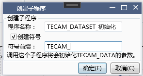
图3 Create Subroutine
After clicking OK, a newly created subroutine is obtained,
Regarding the creation of symbols:
Select 'Create Symbol' and fill in the symbol prefix. All related parameters will be named a symbol in the format of 'symbol prefix+parameter name'.
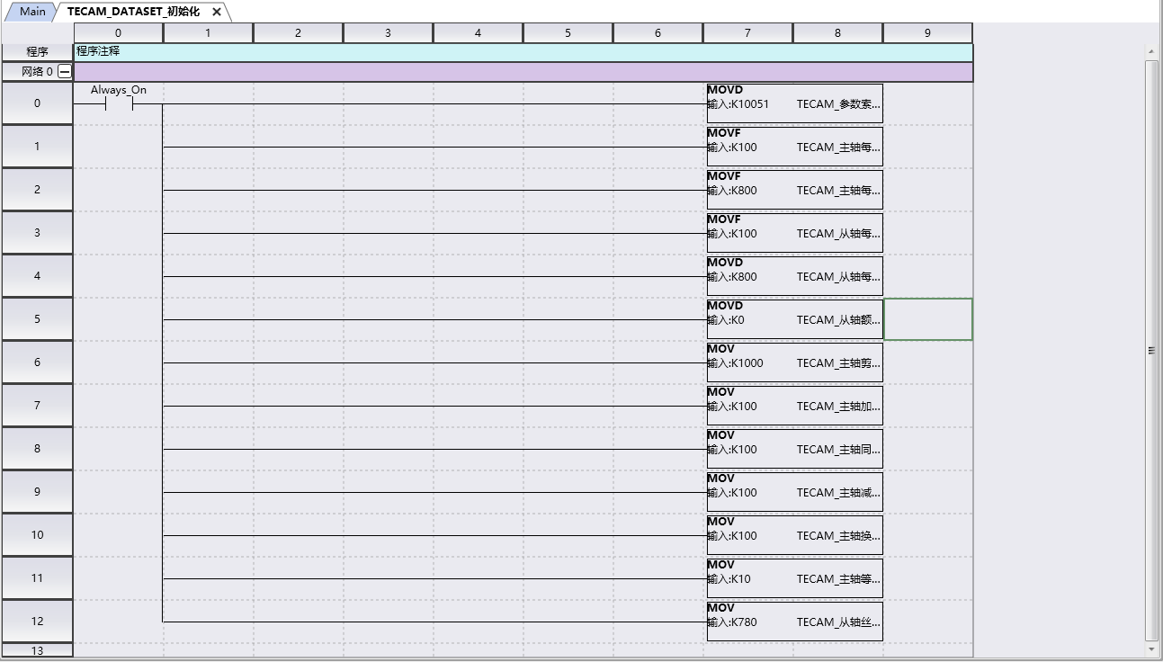
图4 Create Subroutine
At this point, the TECAM-DATA SET cam table has been set up, and the subsequent subroutine needs to be called in main.
1.4.1.2. TECAM instruction setting interface
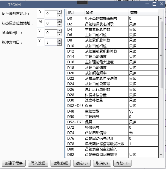
图5 TECAM Instruction Setting Interface
**Pulse output port: * * The pulse output port of the follower axis that follows the cutting
**Pulse direction port: * * Follow the pulse direction port from the axis of the shear follower
Spindle type::
A. The selection of Y (refresh immediately) for the spindle pulse output port that follows is essentially to follow the pulse counting corresponding to the Y port inside the PLC
B. If the number of pulses returned by the AB phase following the servo is selected as CV (the AB phase of the pulse needs to be differentially converted to the collector and connected to the high-speed counting port of the PLC), it will occupy two high counting ports. If the correction signal (X0, X1, X6) still needs to be enabled, the available correction signal may only be the next one; If the response speed of the servo is fast enough and there is no loss of pulses (servo pulse frequency below 180kHz), it is generally recommended to choose Y
C. If following the virtual spindle, select Vy (immediately read D register data)
- Note: Differential to collector electrode method**
The AB differential output of the servo is a 5V signal with four wires: A+, A -, B+, and B -
2) The X input terminal of the PLC requires a 24V signal, and only two wires are connected to the high count dual counting circuit
In order to adapt to the output of the servo, a differential collector circuit board must be added to convert 5V to 24V, and four wires must be converted into two wires A and B for output. At this time, A is connected to X0, B is connected to X1, and 24V is connected to S/S. By calling EHCNT, the pulse counting of the servo encoder can be completed
! [Hardware Manual] (./TECAM~/Images~/pic16. png)
Spindle position index: Determine the specific axis. If Y is selected as the spindle type, filling in 0 represents Y0, filling in 1 represents Y1, and so on
Cam start signal: No selection for fixed length follow-up cutting
Cam start signal address: default 0 for fixed length cutting
Single cycle compensation signal triggering frequency: usually 2 (enabled only after setting the compensation signal)
Number of cam execution cycles: default 0, cyclic execution
Cam speed limit: set to 1950
Spindle phase adjustment: 0, no phase adjustment
Spindle adjustment phase rate: 2
Stop mode flag: After disconnecting TECAM from the axis stop mode, immediately stop and select OFF, and stop and select ON after the cycle ends
Whether the data remains after disabling: whether the operating parameters remain in their pre disconnection state after disconnecting TECAM, select 'OFF' instead of 'ON'
1.4.1.3. TECAM-DATASET and TECAM usage process
A. After successfully downloading the program, enter monitoring mode
B. Enable M0 and enable TECAM-DATA SET (if you do not want to download the program and still click on write to PLC in the upper level, simply create a subroutine and call it directly; if you modify the data in TECAM-DATA SET, the subroutine also needs to be modified. A convenient way is to delete the atomic program, create a new subroutine and call it)
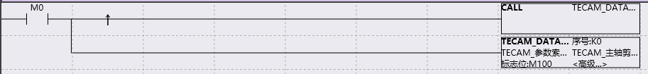
图6 TECAM-DATASET program
C. Write data to flag M100 (in TECAM-DATA SET) and set it to ON. If flag M101 (in TECAM-DATA SET) becomes ON, the write is successful and the next step can be taken; If M101 is still OFF, it indicates that the write was unsuccessful. TECAM-DATA SET needs to be disconnected and enabled again, and the trimming parameters need to be checked for reasonable settings
D. Enable M1 and enable the TECAM instruction (if data in TECAM is modified, the subroutine also needs to be modified. A convenient approach is to delete the atomic program, create a new subroutine, and then call it)
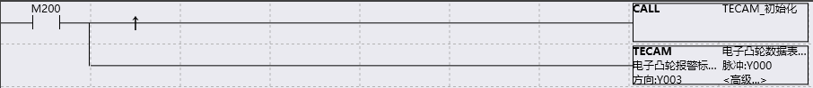
图7 TECAM program
If the power-off hold D register area is not used, a subroutine for MOV data needs to be created because the data written by TECAM will be cleared when powered on. The call to this subroutine can be made at the same time as or before TECAM, but not after TECAM.
F. The spindle is enabled and operation begins.
1.4.1.4. TECAM operation parameter description
1) Phase adjustment is required during operation
(Initial address of running parameter D+102) This is D402, spindle phase adjustment: 2000, unit: pls, fill in the phase adjustment according to actual needs
(The first address of the status flag is M+4) This is M204. The phase adjustment enable flag is ON, which allows for online modification of the spindle phase and takes effect immediately in the next cycle. Each adjustment requires manual triggering and resetting
2) Online modification of trimming parameters
A. Directly modify the value of register D under ladder diagram monitoring or on the screen, and after modification on the editing interface, it needs to be written to the PLC
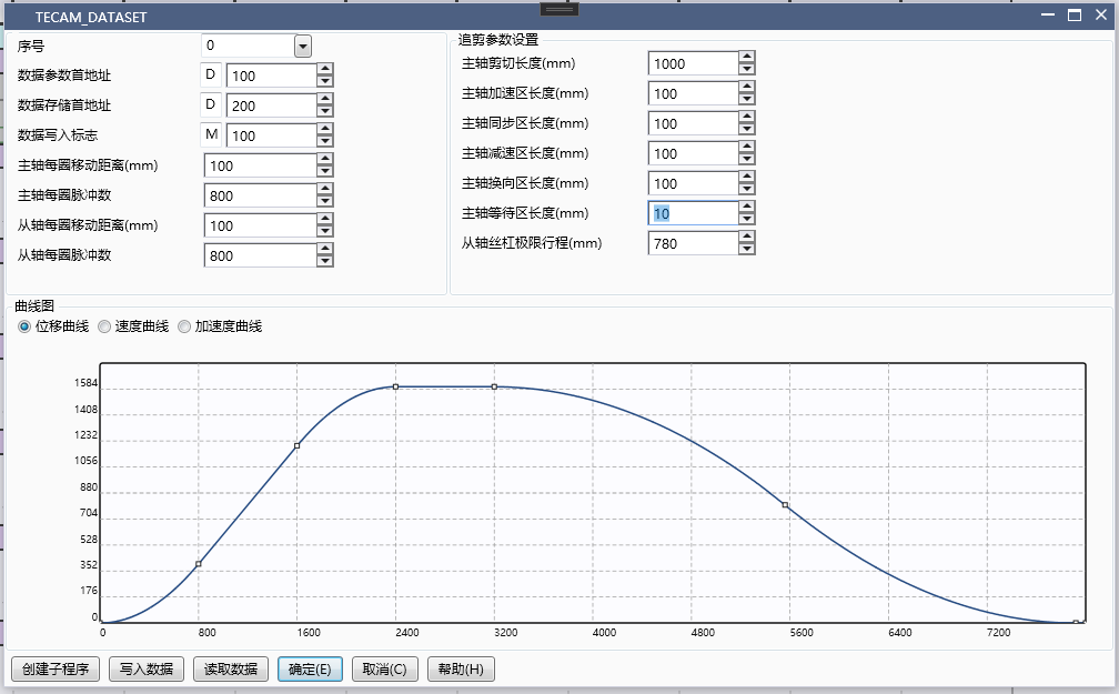
图8 Online modification of trimming parameters
B. Set (write data to the first address of the flag) M100, and when M101 becomes ON, the modification is successful, and the next cycle begins to execute new trimming parameters
1.4.2. Example of Calibration Follow up Cutting
1.4.2.1. TECAM-DATASET setting
The Order number can be selected as 0 or 1, indicating the first or second cam table. For example, fill in 0, and TECAM can call the data in the cam table thereafter,
Initial address of data parameter: Fill in a D register, for example fill in D100. This data will occupy a total of 40 registers from D to D+39
First address of data storage: Fill in an unused D register, for example fill in D200, and for details on the number of registers occupied, please refer to section 1.2
Data write flag: Fill in one M, for example fill in M100, occupying two M registers
Main spindle movement distance per revolution: 100, ignoring all transmission mechanisms in the middle, the actual distance traveled by the machine after one revolution of the main spindle
The number of pulses per revolution of the spindle is 800, which is determined based on the subdivision of the motor or the electronic gear ratio of the servo. It is best to set it to an even number or a multiple of 1000
Moving distance per revolution from the shaft: 100, ignoring all transmission mechanisms in the middle, the actual distance traveled by the machine for one revolution from the shaft
Based on the subdivision of the motor or the electronic gear ratio of the servo, it is best to set the number of pulses per revolution of the shaft to an even number or a multiple of 1000, which is 800
From the rated speed of the shaft: default 0 is calculated based on the maximum pulse frequency of 190kHz; If it is a flying cutter, it can also be set to 2000, with a default unit of r/min
The parameters for trimming can refer to the example, and the specific values can be filled in according to the actual situation.

图9 Calibration and Follow up Cutting Parameter Settings
Click to create subroutine

图10 Create Subroutine
At this point, the TECAM-DATA SET cam table has been set up, and the subsequent subroutine needs to be called in main.
1.4.2.2. TECAM instruction setting

图11 TECAM instruction setting
**Pulse output port: * * The pulse output port of the follower axis that follows the cutting
**Pulse direction port: * * Follow the pulse direction port from the axis of the shear follower
**Spindle type: * * Follow spindle pulse output port selection Y (refresh immediately)
**Spindle position index: * * Determine the specific axis. If Y is selected as the spindle type, fill in 0 for Y0, fill in 1 for Y1, and so on
**Cam start signal: * * Calibration trimming selects X (or M can be used as the start signal), which only takes effect during the initialization process, and modifying the signal during operation is invalid. The start signal must be a rising edge signal. If M is used as the start signal, it needs to be reset after starting.
**Cam start signal address: * * 5, representing the signal of X5. During the cutting process from the shaft, if the main shaft triggers the signal of X5 again, it will not affect the operation of the shaft, nor will it disrupt the operation status of the shaft. Because the cam start signal of the main shaft is only detected after the execution of the shaft, and the cam start signal is not detected during operation.
**Number of triggers for single cycle compensation signal: * * Usually 2 (enabled only after setting the compensation signal)
**Number of cam execution cycles: * * Choose 1. 1 represents performing one trimming from the shaft after detecting the cam start signal, 2 represents performing two trimming from the shaft after detecting the cam start signal, and so on. 0 represents loop execution, usually used in fixed length rather than calibration. Any modifications made during operation will take effect immediately.
**Cam Speed Limit: * * Set to 1950
**Spindle phase adjustment: * * 0, no phase adjustment
**Spindle adjustment phase rate: * * 2
1.4.2.3. TECAM-DATASET and TECAM usage process
A. After successfully downloading the program, enter monitoring mode
B. Turn on M0 and enable TECAM-DATA SET (if you don't want to download the program and still click write to PLC on the upper level, just create a subroutine and call it directly)
C. Write data to flag M100 (in TECAM-DATA SET) and set it to ON. If flag M101 (in TECAM-DATA SET) becomes ON, the write is successful and the next step can be taken; If M101 is still OFF, it indicates that the write was unsuccessful. TECAM-DATA SET needs to be disconnected and enabled again, and the trimming parameters need to be checked for reasonable settings
D. Enable M1 and enable TECAM command
If the power-off hold D register area is not used, a subroutine for MOV data needs to be written because the data written by TECAM will be cleared when powered on. The call to this subroutine can be made at the same time as or before TECAM, but not after TECAM.
F. The spindle is enabled and operation begins.
1.4.3. Example of fixed length flying shear
1.4.3.1. TECAM-DATASET setting
The Order number can be selected as 0 or 1, indicating the first or second cam table. For example, fill in 1. Subsequent TECAM can call the data in the cam table, and the corresponding first address of the running parameter in the TECAM instruction needs to be written as 1, that is, D700 in 3.3.2 should be selected as 1
**First address of data parameter: * * Fill in a D register, for example fill in D500, this data will occupy a total of 40 registers from D to D+39
**First address of data storage: * * Fill in an unused D register, for example fill in D600, and for details on the number of registers occupied, please refer to section 1.2
**Data write flag: * * Fill in one M, for example fill in M300, occupying two M registers
**Main spindle movement distance per revolution: * * 100, ignoring all intermediate transmission mechanisms. The actual distance traveled by the machine after one revolution of the main spindle
**The number of pulses per revolution of the spindle is * * 800, which is determined based on the subdivision of the motor or the electronic gear ratio of the servo. It is best to set it to an even number or a multiple of 1000
**Moving distance per revolution from the shaft: * * 100, ignoring all transmission mechanisms in the middle, the actual distance traveled by the machine for one revolution from the shaft
**From the number of pulses per revolution of the shaft: * * 1600, based on the subdivision of the motor or the electronic gear ratio of the servo, it is best to set it to an even number or a multiple of 1000
**From the rated speed of the shaft: * * default 0 is calculated based on the maximum pulse frequency of 190kHz; If it is a flying cutter, it can also be set to 2000, with a default unit of r/min
**Spindle cutting length (float): * * 200, indicating the length of material cut off from the spindle by the flying shear wheel during the entire flying shear process
**Synchronization zone angle (360 °): * * 30, represents the angle traveled by the flying shear wheel and the spindle at the same speed, and the length traveled is the synchronization zone angle/360 * flying shear wheel circumference
**Number of cutting blades: * * 1. If 2 is filled in, the original axis cycle has been split into two cycles. If the original one rotates one circle from the axis cycle, after splitting, the other rotates half a circle from the axis cycle.
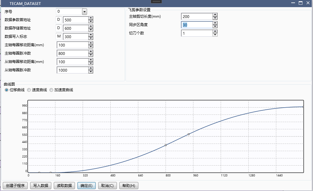
图12 Flying Clipper Parameter Settings
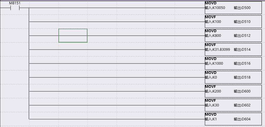
图13 Create Subroutine
Create the subprogram as shown in the right figure, and then call the subprogram in the main program.
1.4.3.2. TECAM instruction setting

图14 TECAM instruction setting
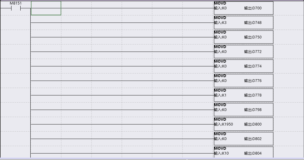
图15 Create Subroutine
Create the subprogram as shown in the right figure, and then call the subprogram in the main program.
**Pulse output port: * * The pulse output port of the shaft followed by the flying shear
**Pulse direction port: * * The pulse direction port from the axis followed by the flying shear
**Spindle type: * * Follow spindle pulse output port selection Y (refresh immediately)
**Spindle position index: * * Determine the specific axis. If Y is selected as the spindle type, fill in 0 for Y0, fill in 1 for Y1, and so on
**Single cycle compensation signal triggering frequency: * * The flying shear is usually 1 (activated only after setting the compensation signal)
**Number of cam execution cycles: * * Select 0. Represents loop execution
**Cam Speed Limit: * * Set to 1950
**Spindle phase adjustment: * * 0, no phase adjustment
**Spindle adjustment phase rate: * * 2
1.4.3.3. TECAM-DATASET and TECAM usage process
A. After successfully downloading the program, enter monitoring mode
B. Turn on M0 and enable TECAM-DATA SET (if you don't want to download the program and still click write to PLC on the upper level, just create a subroutine and call it directly)
C. Write data to flag M300 (in TECAM-DATA SET) and set it to ON. If flag M301 (in TECAM-DATA SET) becomes ON, the write is successful and the next step can be taken; If M301 is still OFF, it indicates that the write was unsuccessful. TECAM-DATA SET needs to be disconnected before enabling and checking if the trimming parameters are set properly
D. Enable M1 and enable TECAM command
If the power-off hold D register area is not used, a subroutine for MOV data needs to be written because the data written by TECAM will be cleared when powered on. The call to this subroutine can be made at the same time as or before TECAM, but not after TECAM.
F. The spindle is enabled and operation begins.
1.4.4. Standard flying shear example
1.4.4.1. TECAM-DATASET setting
The Order number can be selected as 0 or 1, indicating the first or second cam table. For example, fill in 1. Subsequent TECAM can call the data in the cam table, and the corresponding first address of the running parameter in the TECAM instruction needs to be written as 1, that is, D700 in 3.3.2 should be selected as 1
**First address of data parameter: * * Fill in a D register, for example fill in D500, this data will occupy a total of 40 registers from D to D+39
**First address of data storage: * * Fill in an unused D register, for example fill in D600, and for details on the number of registers occupied, please refer to section 1.2
**Data write flag: * * Fill in one M, for example fill in M300, occupying two M registers
**Main spindle movement distance per revolution: * * 100, ignoring all intermediate transmission mechanisms. The actual distance traveled by the machine after one revolution of the main spindle
**The number of pulses per revolution of the spindle is * * 800, which is determined based on the subdivision of the motor or the electronic gear ratio of the servo. It is best to set it to an even number or a multiple of 1000
**Moving distance per revolution from the shaft: * * 100, ignoring all transmission mechanisms in the middle, the actual distance traveled by the machine for one revolution from the shaft
**From the number of pulses per revolution of the shaft: * * 1600, based on the subdivision of the motor or the electronic gear ratio of the servo, it is best to set it to an even number or a multiple of 1000
**From the rated speed of the shaft: * * default 0 is calculated based on the maximum pulse frequency of 190kHz; If it is a flying cutter, it can also be set to 2000, with a default unit of r/min
**Spindle cutting length (float): * * 200, indicating the length of material cut off from the spindle by the flying shear wheel during the entire flying shear process
**Synchronization zone angle (360 °): * * 30, represents the angle traveled by the flying shear wheel and the spindle at the same speed, and the length traveled is the synchronization zone angle/360 * flying shear wheel circumference
**Number of cutting blades: * * 1. If 2 is filled in, the original axis cycle has been split into two cycles. If the original one rotates one circle from the axis cycle, after splitting, the other rotates half a circle from the axis cycle.

图16 Flying Clipper Parameter Settings

图17 Create Subroutine
Create the subprogram as shown in the right figure, and then call the subprogram in the main program.
1.4.4.2. TECAM instruction setting interface

图18 TECAM Instruction Settings

图19 Create Subroutine
Create the subprogram as shown in the right figure, and then call the subprogram in the main program.
**Pulse output port: * * The pulse output port of the shaft followed by the flying shear
**Pulse direction port: * * The pulse direction port from the axis followed by the flying shear
**Spindle type: * * Follow spindle pulse output port selection Y (refresh immediately)
**Spindle Position Index: * * Determine the specific axis. If Y is selected as the spindle type, fill in 0 for Y0, fill in 1 for Y1, and so on
**Cam start signal: * * The calibration flying shear selects X (or M can be used as the start signal), which only takes effect during the initialization process. Modifying the signal during operation is invalid. The start signal must be a rising edge signal. If M is used as the start signal, it needs to be reset after starting.
**Cam start signal address: * * 5, representing the signal of X5. During the process of flying shear from the shaft, if the main shaft triggers the signal of X5 again, it will not affect the operation of the shaft, nor will it disrupt the operation status of the shaft. Because the cam start signal of the main shaft is only detected after the execution of the shaft, and the cam start signal is not detected during operation.
**Single cycle compensation signal triggering frequency: * * The flying shear is usually 1 (activated only after setting the compensation signal)
**Number of cam execution cycles: * * Choose 1. 1 represents performing one flying shear from the shaft after detecting the cam start signal, 2 represents performing two flying shear from the shaft after detecting the cam start signal, and so on. 0 represents loop execution, usually used in fixed length rather than calibration. Any modifications made during operation will take effect immediately.
**Cam Speed Limit: * * Set to 1950
**Spindle phase adjustment: * * 0, no phase adjustment
**Spindle adjustment phase rate: * * 2
1.4.4.3. TECAM-DATASET and TECAM usage process
A. After successfully downloading the program, enter monitoring mode
B. Turn on M0 and enable TECAM-DATA SET (if you don't want to download the program and still click write to PLC on the upper level, just create a subroutine and call it directly)
C. Write data to flag M300 (in TECAM-DATA SET) and set it to ON. If flag M301 (in TECAM-DATA SET) becomes ON, the write is successful and the next step can be taken; If M301 is still OFF, it indicates that the write was unsuccessful. TECAM-DATA SET needs to be disconnected before enabling and checking if the trimming parameters are set properly
D. Enable M1 and enable TECAM command
If the power-off hold D register area is not used, a subroutine for MOV data needs to be written because the data written by TECAM will be cleared when powered on. The call to this subroutine can be made at the same time as or before TECAM, but not after TECAM.
F. The spindle is enabled and operation begins.
1.4.5. Short cutting
The previous examples were all long material cutting, where the entire cutting length is greater than the circumference of the shaft. The movement of the shaft accelerates to the synchronization zone (maximum speed) first, and then decelerates, thus achieving the cutting of long materials.
When the cutting length is less than the circumference of the shaft, short cutting is required. The movement of the shaft is synchronized to the lowest speed in the synchronization zone, slows down to the synchronization zone, and accelerates to the adjustment zone after passing through the synchronization zone. When cutting short materials, the shaft must first accelerate within the adjustment zone and then decelerate to synchronous speed.
Example flying shear parameter settings:
Spindle cutting length: 50
Synchronization zone angle: 90
Number of cutting blades: 1
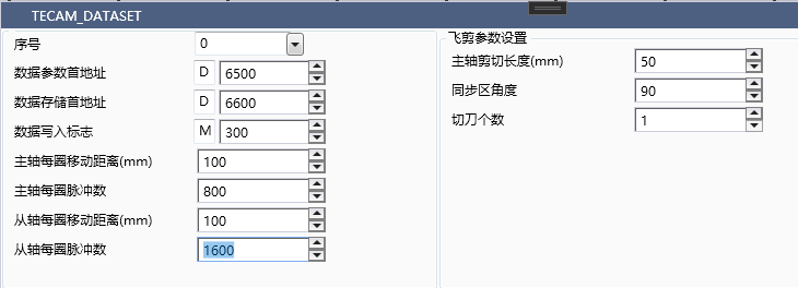
图20 Flying shear parameters
The displacement curve and velocity curve of short material cutting are as follows, with the x-axis as the minor axis and the y-axis as the major axis. The velocity curve clearly shows that the minor axis slows down before reaching the synchronization zone, and then accelerates after passing through the synchronization zone, which is the section with the lowest velocity.
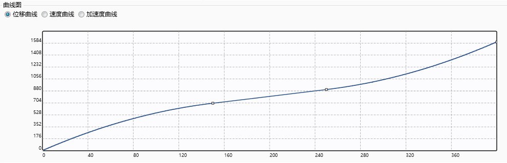
图21 Flying Shear Curve
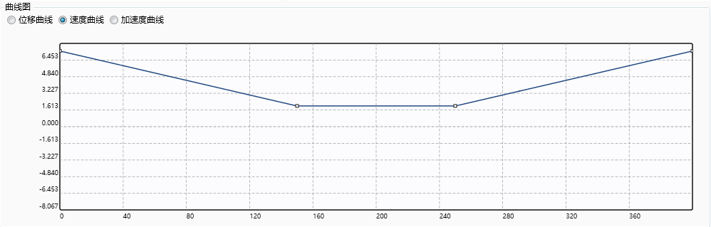
图22 Flying Shear Speed Curve
The setting of TECAM command is consistent with the fixed length flying shear.
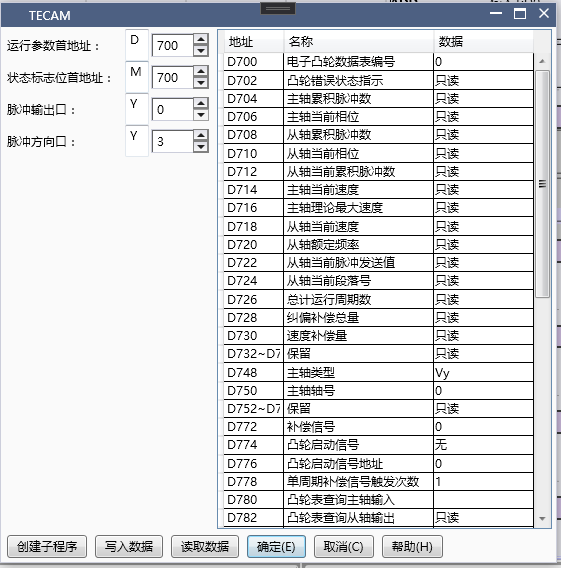
图23 TECAM Instruction Settings
The specific operation and startup steps are consistent with other flying chase cutting processes.
1.4.6. Enable compensation signal
The reason for enabling correction is that it requires very precise correction from the axis zero point, but at the same time, it also requires the correction compensation signal to be stable enough to calibrate the axis back to zero position every time.
1.4.6.1. Related parameters
| Running parameter first address (D700)+offset address | Description | Data type | Register type | Data range | Description |
|---|---|---|---|---|---|
| 28 | Total correction compensation | int | D | Read only, the upper limit of the number of correction pulses is 10% of the number of cycle pulses (i.e. the number of pulses per revolution from the axis), refreshed once per revolution | |
| 72 | Compensation signal | int | D | 0,1,2 | 0: None, 1: Compensation signal X6, 2: Compensation signal X0, 3: Compensation signal X1 is used for axis correction and cannot be used for other external interrupt functions after being enabled |
| 78 | Number of triggers for single cycle correction signal | int | D | Number of triggers for compensation signal in a single cycle of the spindle, usually 1 for flying shear and 2 for chasing shear | |
| 106 | Correction signal compensation feedforward ratio | float | F | >1 | It is only useful when the correction signal is turned on. For correction signals from the axis, it is recommended to set a value greater than 1 |
| First address of status flag bit (M400)+offset address | Description | Data type | Register type | Data range | Description |
|---|---|---|---|---|---|
| 8 | Correction initialization signal | 0: Do not execute, 1: Execute, can be used to clear the correction signal and trigger exceptions during operation |
Set correction signal parameters based on the calibrated flying shear
**Compensation signal: * * 2, enable X0 signal input, at this time X0 cannot be used for other external interrupts
**Number of triggers for single cycle correction signal: * * 1, the number of times the correction signal from the axis is encountered within a single cycle, usually triggered once per cycle, used to correct the deviation from the axis back to the reference position
**Correction signal compensation feedforward ratio: * * 1.1, the feedforward ratio setting needs to be greater than 1.
Follow the normal steps to enable and monitor the relevant parameters for correction, as shown in the following figure
The data type of D702 is DHEX. If D702 displays 0x00010000, it indicates that the correction signal has triggered an abnormality. At this time, setting M408 can clear the error caused by the abnormality. However, the reason for this error is that the correction signal is unstable or the number of correction signals triggered by one revolution from the axis is greater than the set one.
D728 represents the number of correction pulses per revolution, which is refreshed once per revolution and is an accumulated quantity. Generally, the total correction compensation is less than one tenth of the total number of pulses per revolution from the axis.
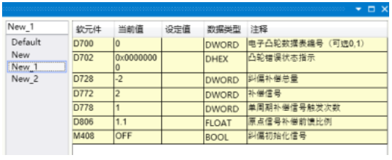
图24 Parameter Settings
The correction signal is to meet the requirement of returning from the axis to the reference position, ensuring that the axis can return to the starting position every time, and to meet the high precision requirements for the axis.
1.4.7. Universal cam (key point)
1.4.7.1. TECAM-DATASET setting
Customizing a cam requires setting various key point parameters, each consisting of five parameters: main axis coordinates, sub axis coordinates, slope, line type, and resolution (the sum of resolutions does not exceed 2048). The position of the key point can be determined by its coordinates, and the shape of the curve can be determined by its slope and line type, thus forming a user-defined cam curve.
Select 0 for the Order number, indicating the first cam table
**The first address of the data parameter is * * D100, which will occupy a total of 40 registers from D to D+39. The value of D100 must be between 10000 and 10049, and D102 must be between 0 and -50
**First address of data storage: * * D200, details on the number of registers occupied. Please refer to section 1.2 for more information
**Data write flag: * * M100, occupying two M registers
**Main spindle movement distance per revolution: * * 100, ignoring all intermediate transmission mechanisms. The actual distance traveled by the machine after one revolution of the main spindle
**The number of pulses per revolution of the spindle is * * 800, which is determined based on the subdivision of the motor or the electronic gear ratio of the servo. It is best to set it to an even number or a multiple of 1000
**Moving distance per revolution from the shaft: * * 100, ignoring all transmission mechanisms in the middle, the actual distance traveled by the machine for one revolution from the shaft
**From the number of pulses per revolution of the shaft: * * 1600, based on the subdivision of the motor or the electronic gear ratio of the servo, it is best to set it to an even number or a multiple of 1000
**From the rated speed of the shaft: * * default 0 is calculated based on the maximum pulse frequency of 190kHz
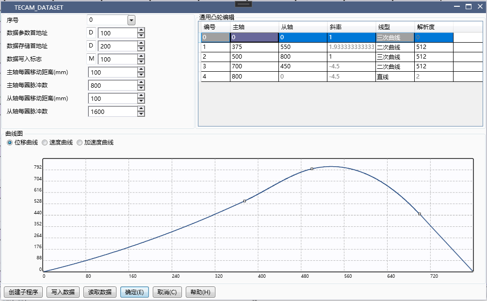
图25 Universal Cam Settings
1.4.7.2. Operation process description::
The first paragraph: When the spindle runs from 0 to 375 and from 0 to 550, this paragraph is a quadratic curve with an endpoint slope of 1.93;
The second paragraph: When the spindle runs from 375 to 500 and from 550 to 800, the curve in this paragraph is a cubic curve with a slope of 1;
The third paragraph: When the spindle runs from 500 to 700 and from 800 to 450, the curve in this paragraph is a quadratic curve with a slope of -4.5;
The fourth paragraph: When the spindle runs from 700 to 800 and from 450 to 0, the curve in this paragraph is a straight line with a slope of -4.5;
When the main shaft passes the end point of the fourth section, it continues to run according to the cam curve from the end position 0 of the shaft, and this cycle is repeated.
1.4.7.3. Explanation about the endpoint::
If the endpoint of the curve returns to the starting point, there will be no deviation in the next cycle; If the endpoint is not at the starting point, there will be a positional offset (the difference between the endpoint and the starting point) for each subsequent cycle, and the total offset will accumulate as the cycle increases.
1.4.7.4. TECAM setting
Running parameter first address: D300, occupying a total of 128 registers from D300 to D426
The first address of the status flag bit is M200, occupying a total of 32 registers from M200 to M231
1.4.7.5. TECAM-DATASET and TECAM usage process
A. After successfully downloading the program, enter monitoring mode
B. Turn on M0 and enable TECAM-DATA SET (if you don't want to download the program and still click write to PLC on the upper level, just create a subroutine and call it directly)
C. Write key point data into the data storage address, set the data write flag M100 (in TECAM-DATA SET) to ON. If the flag M101 (in TECAM-DATA SET) becomes ON, the write is successful and the next step can be performed; If M101 is still OFF, it indicates that the write was unsuccessful. TECAM-DATA SET needs to be disconnected before enabling and checking if the trimming parameters are set properly
D. Enable M1 to enable the TECAM instruction. If the power-off hold D register area is not used, a subroutine for MOV data needs to be written because the data written by TECAM will be cleared when powered on. This subroutine can be called at the same time as or before TECAM, but not after TECAM.
F. The spindle is enabled and operation begins.
1.4.8. Universal cam (midpoint/insertion point)
1.4.8.1. TECAM-DATASET setting
In the insertion point mode, only the number of pulses for the spindle and slave axes needs to be set, without the need for the number of pulses per revolution and distance per turn for the spindle and slave axes. The motion curve is calculated based solely on the number of pulses for the slave axis corresponding to the number of pulses for the spindle.
Select 0 for the Order number, indicating the first cam table
Initial address of data parameter: D6100, the value of D6100 must be between 0-9999
D6102 is between 0-2048, with a maximum data depth of 2048
First address of data storage: D6200, details on the number of registers occupied. Please refer to section 1.2 for details. One spindle or slave coordinate occupies one double word register
Data write flag: M100, occupying two M registers
Starting number of the midpoint: the value of D6100, which is 0 when first written and serves as the starting number for the modified content in subsequent modifications
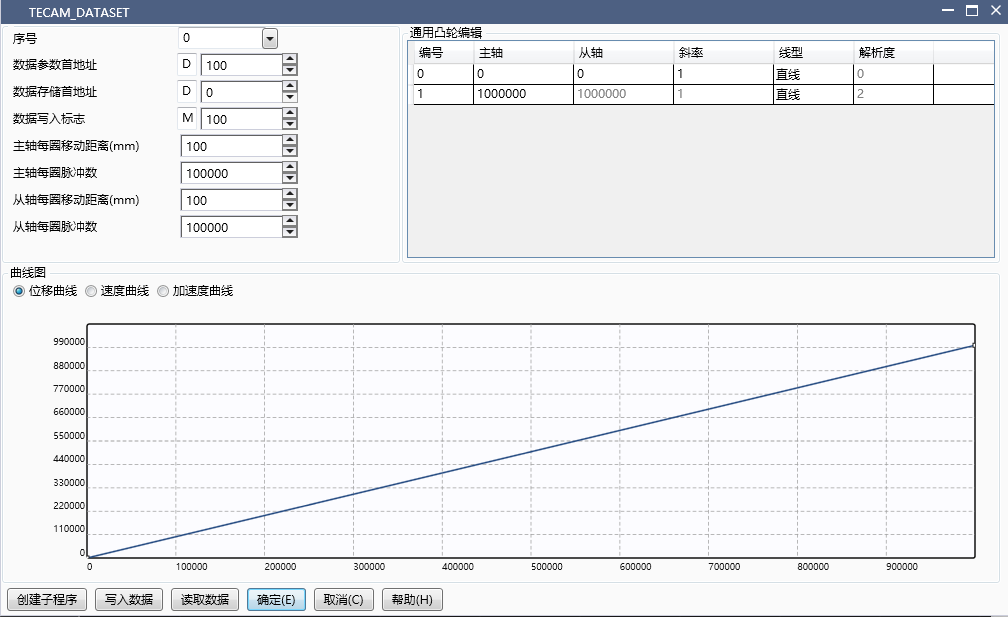
图26 Universal Cam Setting 1
Setting of TECAM instruction
Fixed length and calibration can be specifically selected, and the parameters set here are fixed length parameters
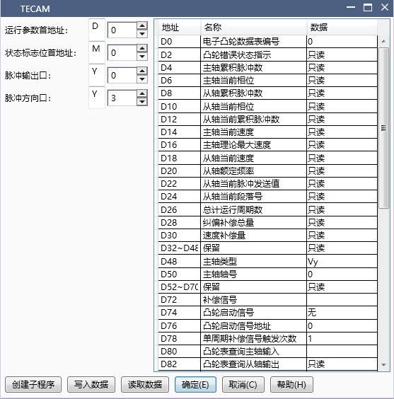
图27 Universal Cam Setting 2
The startup in this mode is consistent with the keypoint mode, and manual data writing to the storage area is also required; When the number of points exceeds the upper limit of the D register, the starting number and depth can be modified and written multiple times.
All four modes support dynamic modification of cam tables. After modifying the corresponding register area of TECAM-DATA SET, the rising edge to refresh flag is triggered, and the next cycle change takes effect after the calculation is completed; The keypoint and midpoint patterns also support local data modification, and specifying the index and depth will modify the corresponding positions and lengths of the points.
1.4.9. Types of errors and their elimination
1.4.9.1. Speed compensation
Compared with mechanical camshafts, electronic camshafts have a hysteresis characteristic of following, which means that the position can only be calculated for following after detecting the change in the spindle phase from the shaft. The TECAM instruction is timed calculation, so the lag distance is proportional to the spindle speed, manifested as the faster the spindle speed, the more the amount of lag from the shaft.
When the speed of the electronic cam remains constant during operation, the hysteresis is also constant, which can be processed through the spindle phase adjustment function. Otherwise, the speed compensation function needs to be turned on, and the default speed compensation coefficient offset address D110 is 0 (i.e. closed state). It is recommended to set the initial value of the speed compensation coefficient to 1 (float), and then run the electronic cam to observe whether the phase lag of the slave shaft increases or decreases when switching from low speed to high speed. If it increases, slightly increase D110. If it decreases or even leads, slightly decrease D110 until the coefficient is appropriate and the relative phase between the master and slave no longer changes with speed.
The speed compensation coefficient can be adjusted in real-time and can be adjusted during operation. Once set appropriately, the value can be written into TECAM initialization and will not be modified.
1.4.9.2. Spindle phase sampling amplification factor
When starting to run the electronic cam, it was found that the cutting length was incorrect and the speed ratio in the synchronization zone was not suitable. If there was a significant difference at this time, it indicates that the quantities related to pulse equivalent and cutting length were not set accurately (single cycle pulse number/single cycle pulse distance/cutting length/flying shear wheel diameter, etc.), or that the equivalent was too large, resulting in one pulse moving too far from the shaft and insufficient accuracy. It is recommended to check these parameters; If the difference is very small and the accumulated difference can only be seen after running it many times, it may be due to limited calculation accuracy (for example, the pulse number corresponding to the cutting length is 10000.001, but the cam table can only record integer 10000, and the error caused by limited accuracy when π participates in the operation). At this time, the spindle phase sampling amplification factor (offset address D108, default is 1, float) can be used to adjust it. After filling in the value, the sampled spindle phase will be multiplied by this factor as the new phase. For example, after running 1000 revolutions, if it is found that the spindle is leading by a distance equivalent to one pulse, then the value of D108 is approximately the number of spindle cycle pulses; 1000/(spindle cycle pulse count&# 42; 1000+1).
D108 can also be used to adjust the above parameters when they are not appropriate, which is equivalent to modifying the number of pulses per revolution of the main shaft. It can be adjusted during operation without going back to modify the ladder diagram, but at this time, the adjustment range is relatively large, which is generally not recommended.
D108 can also be used literally to enlarge or reduce the spindle sampling values by a certain magnification, but users need to be careful to avoid causing spindle phase mutations and other situations.
The accuracy of D108 is a single precision floating-point number (6-7 decimal places), so a zeroing calibration process is still necessary for projects that have been running in large quantities for a long time.
1.4.9.3. Spindle phase adjustment
After adjusting the cutting length and speed compensation appropriately, the cutting position can be adjusted. By adjusting the spindle phase (offset address D102, signed integer, unit: pulse number), the relative position between the spindle and the slave axis can be moved as a whole. After setting the adjustment distance, enable the spindle phase adjustment signal (offset address M4), and the spindle phase will change the set distance accordingly.
When adjusting the distance is large, it is equivalent to a sudden change in the phase of the main axis, which will cause a speed change from the axis. It is recommended to gradually adjust it in multiple times, or set the phase adjustment steps (offset address D104, positive integer) to be larger.
The spindle phase adjustment is triggered by the rising edge of the spindle phase adjustment signal, and the set distance is adjusted each time it is triggered.
1.4.9.4. Correction compensation
In addition to adjusting the parameters of the electronic cam, we also provide external interrupt signals to correct the fluctuation of the actual shear distance around the theoretical value caused by small material deformation or mechanical clearance. This can be selected at offset address D72, and it is necessary to set the number of times the correction signal will be triggered within one spindle cycle (offset address D78). For the flying shear using the flying shear wheel, it is usually once, and for the reciprocating follow-up shear, it is usually twice.
The correction signal is generally recommended to be installed a certain distance before the cutting point. After detecting the correction signal, the electronic cam will sample the current spindle phase and compare it with the first recorded position, and compensate for the difference with the corresponding length of phase. In the default state, the compensation amount is the detected distance. If the correction compensation is enabled and the fluctuation of the cutting position is found to increase, the proportional coefficient of the correction signal for offset address D106 (default is 1, float) should be appropriately reduced. If the correction effect is not obvious, it should be appropriately increased, generally slightly greater than 1. It can be observed that the cumulative correction distance D28 fluctuates more appropriately within ± 1 pulse range.
The reference position for correction can also be obtained manually (offset address D84). In the default state of 0, the spindle position at the first trigger is used as the reference position. If it is not 0, the spindle position filled in with this address will be used as the correction reference position. When the correction signal is installed at the starting position, the number of spindle cycle pulses can be filled in here; The update of the reference position is described in the correction initialization signal (offset address M8).
The activation of the correction signal should be carried out at the end of parameter adjustment. The recognition range of the correction signal is the distance between 1/20 of the spindle cycle pulse number before and after the recording position. Otherwise, it will be considered an illegal signal. The total correction amount will also be recorded and can be checked at offset address D28. When the total correction amount exceeds 1/10 of the spindle cycle pulse number, it will also be considered that the offset is too large; When a correction exception occurs, the correction distance will maintain the last valid amount and will not be refreshed. At the same time, there will be an error code prompt.
Even if the correction distance is within the default legal range of the electronic cam, if the pulse number deviates too much, it will trigger a runaway alarm due to the high pulse frequency during correction. Therefore, if the shear distance changes greatly due to material deformation or other reasons, please adjust the corresponding cam table parameters.
The correction signal occupies the external interrupt port, and the corresponding port's external interrupt and high-speed counting functions are not available when in use.
1.4.9.5. Drive and mechanical stiffness errors
The PLC sending pulses to the actual mechanical operation is not completely synchronized, and it also needs to go through servo or stepper drive processing and subsequent mechanical transmission. This step is related to factors such as drive performance, parameter settings, and load capacity. The errors caused by this can often be judged by reading the instantaneous spindle count and slave spindle pulse count through a high-sensitivity detection switch near the cutting point, and comparing them with the actual cutting effect to determine the size of this error; If there is no external signal, the spindle count can also be subtracted from the spindle cycle pulse number (TECAM offset address D32) as the actual spindle phase. Each time this value passes through a fixed point in the synchronization zone, the sub axis pulse count value is sampled. If the spindle sampling is accurate, the sub axis pulse count here is the theoretical position of the machine. If the value is stable but there is fluctuation in the actual cutting, there is an error source in this item, and it is necessary to optimize the relevant drive or machine;
If there is a certain pattern in this error, or the deviation size can be obtained through external signals, it can also be compensated through spindle phase adjustment, as detailed in FAQ4.0.3. However, it is recommended to prioritize eliminating this error by adjusting the drive and machinery, as this error may change during operation after project debugging, and it is not convenient to adjust it again.
1.4.10. FAQ
1.4.10.1. How to make the cam start running from a specific phase after re enabling the disengagement of the master and slave shafts and moving past the cutting blade position?
With the help of the data retention function after deactivation (offset address M6), before re enabling, the current phase of the spindle (offset address D6) and the current phase of the slave shaft (offset address D10) are rewritten to the starting phase to be set. The slave phase corresponding to the spindle phase can be obtained through the cam table query function (see TECAM parameter offset address D80 D82 M10 explanation).
1.4.10.2. How to achieve the goal of resuming the operation of the cam from the stopped state when it stops halfway and restarts after power failure?
Set the TECAM related parameter registers (including D and M) in the power-off hold area, and set whether to hold (TECAM offset address M6) to 1 after the cam is enabled. When stopping, disable the TECAM instruction, then turn off the power, and when powered on again, it can continue to operate in its original state.
1.4.10.3. How to adjust the lower blade position without stopping the machine if the lower blade position is incorrect during operation?
By using the spindle phase adjustment function (TECAM offset address M4), the spindle phase adjustment distance (offset address D102) and adjustment steps (offset address D104) are set, and the rising edge signal of M4 is given. The spindle will gradually complete the spindle offset within the set time (D104 calculation 1ms cycle), thereby controlling the lower tool position; Another method is to modify the length of each area before the synchronization zone, enabling TECAM-DATA SET to calculate the signal (TECAM-DATA SET offset address M0), so as to adjust the position of the lower blade by changing the axial travel before the lower blade. This method will cause changes in the cam table and is generally not recommended.
1.4.10.4. During the calibration process, it was found that there was a loss of cycles and an abnormal start signal was triggered. What is the reason for this?
There is a situation where the next color mark signal has already arrived before the previous cycle is completed. At this time, it is necessary to shorten the total cutting length to ensure that the cutting length is always less than the color mark spacing. It is also recommended to reduce the length of the waiting area to minimize the impact on the return area; For the flying shear without waiting area, it is not recommended to use the start signal because the speed during the waiting period is 0, which will cause the mechanical operation to be discontinuous. It is recommended to use the color code signal as the correction signal.
1.4.10.5. What is the reason for the high risk of runaway alarms during operation?
The direct cause of the flying car alarm is that the theoretical transmission value from the axis exceeds the upper limit of the set pulse frequency in a short period of time. When using the 1ms calculation cycle version, it is particularly important to note that the speed ratio between the axis and the spindle should not be too high. For example, if the spindle phase changes by 1, if the axis changes by more than 200, the corresponding pulse frequency within 1ms will exceed 200k. At this time, it is necessary to adjust the parameters such as the number of single cycle pulses from the master and slave axes appropriately to reduce the speed ratio; When using functions such as speed compensation, spindle phase adjustment, and correction that involve adjusting the spindle phase, it is necessary to increase the number of spindle phase adjustments appropriately (TECAM offset address D104, shared by the aforementioned three functions) to mitigate sudden changes in spindle phase and avoid causing Flying.
1.4.10.6. Where is the correction signal installed?
It is recommended to install the follow-up cutting at a distance in front of the synchronization zone to ensure that the correction is completed before the cutting blade action; If the flying shear is used to correct the cutting length, it is recommended to install it at a certain angle before the axis cutting point. If it is calibrated, it is recommended to install it at a certain distance before the main axis enters the cutting point.