1. HMI drawing import HMIBLOCK
1. HMI drawing import HMIBLOCK
1.1. Instruction Description
This instruction is only valid for some models Please check with our enginner or sales;
The PLC mode with 10 pulse output, high-speed pulse ports are Y0~Y7, Y10~Y11, with a pulse frequency range of 0~500KHz. The mini series PLC pulse output ports are Y0~Y3, with a pulse frequency range of 0~200KHz;
The function of this instruction is to complete the drawing of imported graphics in a specified plane system;
This instruction must be used in conjunction with the special HMI firmware for display and control;
Currently, importing graphics only supports graphics composed of line and arc commands in AutoCAD, and only supports importing saved DXF files.
1.1.1. Instruction usage instructions
In AutoCAD software, use the line and arc commands to draw design graphics. It should be noted that the size of the plane system needs to be determined, and the drawn graphics cannot exceed the boundaries of the plane system. The drawing method for importing graphics is absolute coordinate drawing, so the origin of the plane system needs to coincide with the origin of the world coordinate system in AutoCAD. The dimensions in AutoCAD are all in mm units. After drawing, confirm that all line segments in the graphics are the ones that need to be drawn, and save them as 2004dxf;
Perform graphic conversion by clicking on the path: Main Menu ->Pulse ->Graphic Conversion. Select the. dxf file saved as in the previous step to generate a new. ssd file format. Transfer the. ssd file to a USB drive, preferably in the same directory, and the path in the subdirectories must be in English. The size of a single converted. ssd file should not exceed 500KB;
Add a 'function button' in SK6.0 HMI and select the function as' Slave devices IP config ';
Insert the USB flash drive into the HMI's USB jack, press the above function button, and enter the graphic preview interface, as shown below.
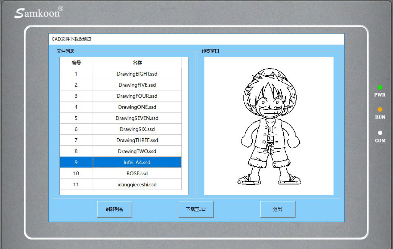
图1 Graphic Preview Interface
If no graphics are detected, click the 'Refresh List' button, select the graphics to be drawn from the left list, click 'Download to PLC', and wait for the progress bar to complete the download. At this point, the graphics have been downloaded from HMI to PLC;
The ladder diagram in PLC is as follows, where D6000 sets the parameter as the plane system number, and the graphics will be drawn in the corresponding plane system. D6001 (D6002) is the drawing speed unit in mm/s. Note that the coordinate data in CAD graphics are all floating point numbers in mm, so the speed is also a floating point number. MOVF must be used to assign the speed. D6003 is the acceleration time, D6004 is the deceleration time, in ms, D6005 is the type of control bit Y or M, writing 0 is Y, writing 1 is M, D6006 is the control bit number, if D6005 writes 0 and D6006 writes 10, it means Y10 represents the control bit status (i.e. Y is the control bit in base 8). If D6005 writes 1 and D6006 writes 10, then M10 is the control bit (i.e. M is the control bit in base 10). The meaning of the control bit is the same as the line state in the BLOCK instruction, representing solid or dashed lines. When the solid line is used, the control bit is ON, and when the dashed line is used, the control bit is OFF. D6007 (D6008) is the X-axis offset of the entire graphic, and D6009 (D6010) is the Y-axis offset of the entire graphic. By adjusting this offset, the position of the graphic in the coordinate system can be adjusted. The parameter is a floating-point number and must be assigned using MOVF. D6011 is in pause mode. If it is zero, there will be no pause. If it is 1, there will be a pause at the intersection of the solid and dashed lines. D6012 is a software component that restarts after a pause. In the example, it can be set to M12 to restart the drawing after a pause at the intersection of solid and dashed lines;
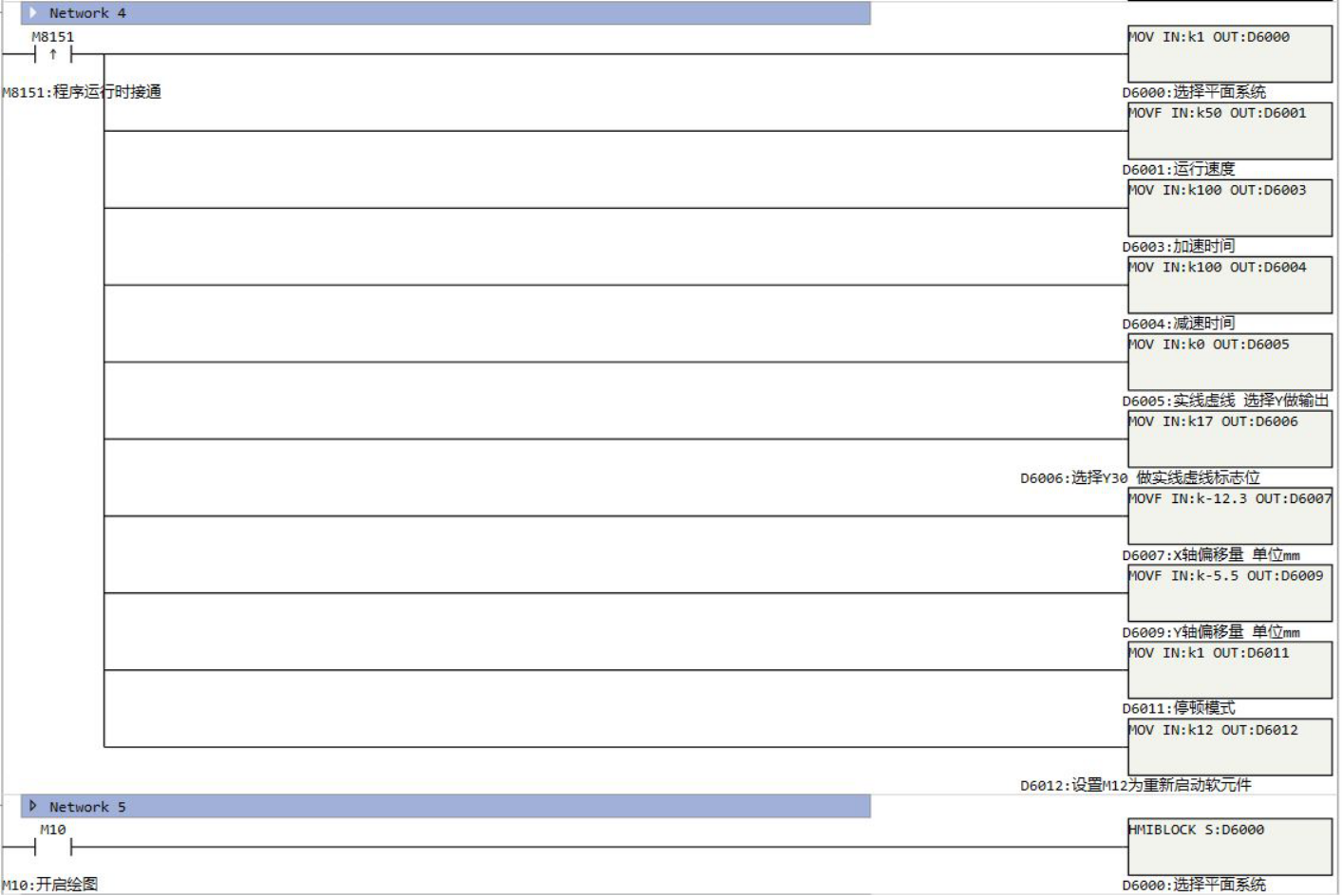
图2 Sample program
After completing the above steps, enable the HMIBLOCK command to start drawing;
To achieve real-time display of trajectories, it is necessary to select 'Start HMI Real time Display' in the 'Plane System Settings' of the PLC and enter the data address. The' XY Trend Chart 'control needs to be added to the HMI, and its' Read Address' must be the same as the data address set in the' Plane System Settings' of the PLC. For other settings of this control, please refer to the HMI help document. The following figure shows the process of HMI real-time display of PLC drawing trajectories;
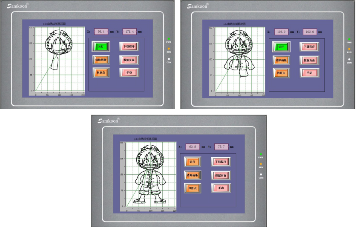
图3 Real time display of drawing trajectory
1.1.2. Attention:
For high-speed pulse output, it is designed for external high-speed devices. To count the pulses, only the high-speed pulse input counter can be used, and internal counters or Y edge changes cannot be used for counting. When used as a high-speed output, it cannot be used as a regular output port;
The OFF time of transistors has the characteristic of being prolonged under light loads. So, when responsiveness is required, please design a load resistor to increase the load current when the load is lighter;
The pulse accumulation count registers (D8140~D8146) are important registers that can be read and written. When a new value is written, the count will be added or subtracted based on the new value;
Due to the directional output of the pulse in this instruction, the pulse accumulation count registers (D8140~D8146) count according to the direction;
When outputting high-speed pulses, the values in the pulse accumulation count registers (D8140~D8146) are discontinuous and constantly changing. When used for judgment, please use size comparison instead of equal judgment;
Do not set the acceleration and deceleration time too small, otherwise there will be no acceleration and deceleration effect;
The pulse is sending a flag bit, such as M8134, which only represents whether Y0 is outputting a pulse. If it is necessary to detect whether a pulse is being sent in plane system 1, use M8144. When running the interpolation command, if any axis in the plane system sends a pulse, this bit will be ON;
The speed and XY axis offset of the HMIBLOCK instruction must be assigned using the MOVF instruction;
The size of a single. ssd file should not exceed 500KB;
The HMIBLOCK instruction cannot be used simultaneously by multiple instructions, and only one HMIBLOCK instruction can be used at a time;
When downloading a graphic using HMI, it will automatically overwrite the previous downloaded graphic.
If the frequency of multiple pulse pulses exceeds 200K, a pull-up resistor needs to be added to the pulse output port to ensure that the pulse waveform is not distorted. The pull-up voltage is 24V, and the recommended pull-up resistor is 1K.