1. Import process CAD graphics HMIPLINE
1. Import process CAD graphics HMIPLINE
| Corresponding Command | Annotation/Description | Parameters |
|---|---|---|
| HMIPLINE | With Process CAD Drawing Instructions | Plane System Number |
| Exercise to the point | ||
| Manual automatic mode switching position | ||
| Manually move to the next point | ||
| Manually move up to the next position | ||
| Destination coordinate display address | ||
| Save endpoint coordinate file location | ||
| Export selected file locations | ||
| Select file address | ||
| First address of file information output | ||
| Refresh file list bit | ||
| Clear all file locations | ||
| Delete selected file location | ||
| End flag position |
1.1. Instruction description
This instruction is only valid for some models ,please check with our enginner or sales;
Its the PLC mode with 10 high-speed pulse output , Y0~Y7, Y10~Y11, with a pulse frequency range of 0~500KHz. The mini series PLC pulse output ports are Y0~Y3, with a pulse frequency range of 0~200KHz;
The function of this instruction is to draw CAD graphics with process parameters in a specified plane system, suitable for various occasions such as drilling, dispensing, spot welding, etc;
This instruction must be used in conjunction with the special HMI firmware for display and control;
Currently, importing graphics only supports graphics composed of line and arc commands in AutoCAD, and only supports importing saved DXF files.
1.1.1. Instruction usage instructions
in AutoCAD software, only the functions of lines, arcs, and circles can be used to draw design graphics, and after the drawing is completed, the 'explode/explode' function needs to be used to convert the graphics into a single entity. It should be noted that the drawing method for imported graphics is absolute coordinate drawing, and the origin of the plane system needs to coincide with the origin of the world coordinate system in AutoCAD. The dimensions in AutoCAD are all in mm units. When drawing, the size of the plane system needs to be determined, and the drawn graphics cannot exceed the actual boundaries of the plane system. When positioning points need to be implemented, use a straight line to connect all positioning points (only straight lines can be used to connect each positioning point), and then decompose/explode the line into a single line segment. The endpoint of the straight line segment is the point that needs to be positioned. When specific trajectory movements need to be achieved, use the functions of lines, arcs, and circles to draw corresponding graphics, and finally decompose/explode them into a single graphic element. After drawing, confirm that all line segments in the graphic are the ones that need to be drawn, and save them as a 2004dxf format file;
Use the display control CAD software SamCAD to open the saved DXF file. For specific instructions, please refer to the SamCAD user manual. As shown in the following figure, it is a CAD drawing controlled only by point positions. The dashed line in the figure is the transition line, which is the line segment running from the origin to the first point. This line segment is not drawn by the user and is automatically connected by the software;
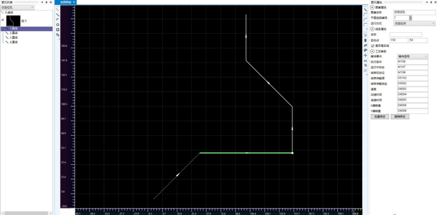
图1 SamCAD software image
In the image properties on the right side of the interface, the image name column can change the image name, but it needs to be consistent with the final saved. ssd file name. The plane selection number allows you to choose the running plane number, which is useless. The actual running plane system needs to be set in the HMIPLINE command. In the operation mode bar, you can choose between * * positioning point only mode * * and * * running trajectory mode * *. In positioning point only mode, the graphic elements can only be straight lines, while in running trajectory mode, the graphic elements can be straight lines, arcs, and circles. In addition, the positioning point mode only allows for manual switching of positioning points, as detailed in the HMIPLINE command parameters;
Select the corresponding line segment directly in the graphic, or select a line segment from the list on the left. The selected line segment will be highlighted in green, and the process parameters of the line segment will be displayed in the attribute bar of the graphic element on the right, as shown in the following figure. The process parameters are parameters that are connected to the PLC action. The process parameters of each line segment can be set separately. For the convenience of control, different graphic elements can also be set to the same D register or M component for control. The meanings of each parameter are as follows:
| Line segment parameters | Detailed description |
|---|
Waiting events are divided into three types: waiting signal, waiting time, and pulse transmission completion. Select the wait signal. When the HMIPLINE instruction is enabled, the action of the line segment will be executed when the execution condition flag (M106 in the figure) is turned on; When selecting the waiting time, after the previous line segment is completed, wait for the corresponding time (K500 in the figure, which is 500ms) and run the line segment; After selecting the pulse transmission completion, that is, after the upper segment runs, immediately run the segment, and the execution condition column set in the figure is invalid.
| Execution conditions | correspond to different waiting events and set different contents. When the waiting event is a waiting signal, the execution condition can only be for the M component, and M conduction is considered to meet the execution condition. It should be noted that the execution condition is set by the user ladder diagram and also needs to be reset by the user ladder diagram. If multiple line segments set the same execution condition, then to avoid running errors, the execution condition needs to be reset before the next line segment runs. When the waiting event is ATC time, the execution condition is time, which can be set as a K constant or dynamically changed in the D register. When waiting for the completion of pulse transmission, the execution condition is invalid and can be written to K0. |
| Running flag | When the PLC is running the segment, the running flag will be set by the PLC. After the segment ends running, the PLC will reset the flag. It should be noted that the PLC will automatically set and reset the flag, and users do not need to perform ladder diagram control on it. It can only be used as a conditional judgment. |
| End flag | When the line segment ends running, this flag will be set by the PLC. This flag can be used as a trigger for the action at that point. For example, when a hole needs to be punched at that point and the flag position is reached, the system will run to the designated position, which can trigger the punching action. It should be noted that this position is set by the PLC and requires the user to reset it using a ladder diagram. |
| End transmission source | End transmission address. When the line segment ends running, assign the value from the end transmission source to the end transmission address. For example, in spot welding equipment, different points may correspond to different welding angles. The end transmission source can be set to the corresponding angle as an important operating parameter. The end transmission source can be set to a K constant, which is a floating-point number. When using it, it should be noted that it can also be set to a D register. The end transfer address can only be set to the D register. |
| Speed | The speed at which the line segment runs, measured in millimeters as a floating point number, can be set as a K constant or dynamically changed in a D register. For ease of control, different line segments are often set to the same speed parameter. |
| Acceleration time and deceleration time | The acceleration time and deceleration time of the segment during operation are single word integers that can be set as K constants or D registers. |
| X. Y offset | Due to the fact that the graphics drawn by CAD software are theoretical graphics, there may be certain deviations in actual use due to factors such as equipment assembly and fixture clamping. This deviation can be corrected by X and Y offsets, which are the endpoint coordinates of the corrected line segments. Each line segment can be set with a separate offset, which is measured in millimeters and is a floating point number. It can be set as a K constant or D register. When all points are set with the same offset, it can be regarded as the overall offset of the graphics. When selecting only positioning points in the operation mode bar, the offset of different elements can be set to different values. When selecting the operation trajectory in the operation mode, the offset of different elements must be set to the same value, and only the overall offset can be set. |
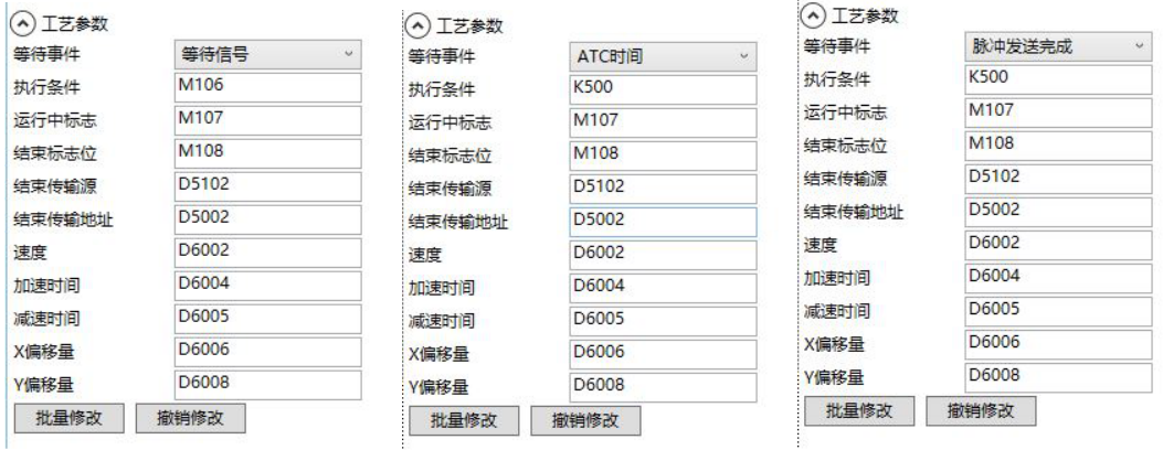
图2 line parameter
Download and develop the underlying layer in 6.0 HMI, add a 'function button', and select the function as' Slave devices IP config ';
Insert the USB flash drive into the USB jack of the HMI, press the above function button, and enter the graphic preview interface, as shown below.
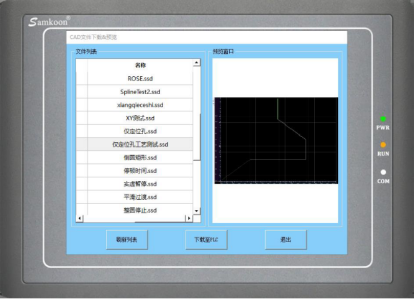
图3 image preview
- If no graphics are detected, click the 'Refresh List' button, select the graphics to be drawn from the left list, click 'Download to PLC', and wait for the progress bar to complete the download. At this point, the graphics have been downloaded from HMI to PLC;
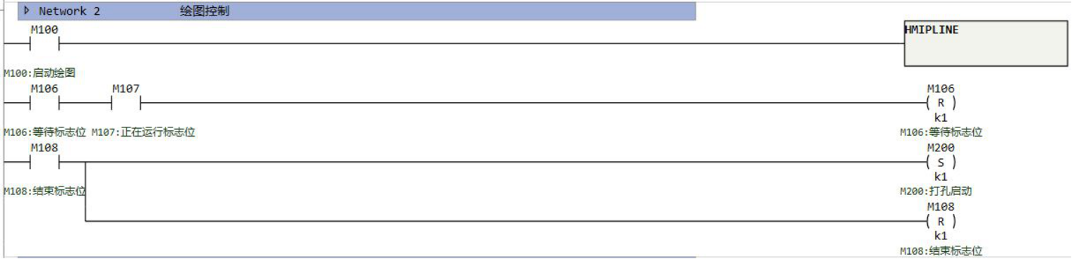
图4 sample program
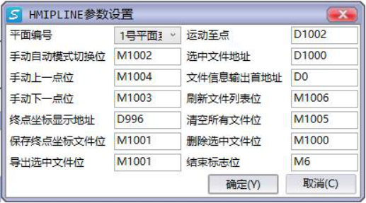
图5 HMIPLINE command edit window
| Instruction Parameters | Detailed Description |
|---|---|
| Plane Number | Select the plane system to run on the graphic. For information on setting up the plane system, please refer to the help document, Plane System Settings; |
| Manual and automatic mode switching position | When only point-to-point control is used, automatic control and manual control can be selected. When the switching position is OFF, it is automatic control. If the HMIPLINE command is enabled, the graphics will be run according to the process parameter settings. If the switch position is ON, it is a manual control, and the process parameters of the graphic are invalid. It is necessary to manually switch between the previous and next points by manually marking the previous and next points. |
| Manual up and down point control | In manual mode with only point control, the up and down points can be manually switched. |
| End point coordinate display address | Save end point coordinate file location, export selected file location, currently does not support corresponding functions, can be set arbitrarily; |
| Motion to Point | When only controlling the point position, except for the previous and next points, the designated point position can be set through this D register. In manual mode, clicking on the next point position can run to any set point position. In automatic mode, set the specified point, and when the command is enabled, run directly from the set point. |
| Select file address | Select the saved graphics in the PLC as the graphics to run. The PLC can save 20 graphics files, and users can select the file number to run based on this register. |
| First address of file information output | Select a D register address as the storage address for the graphic file name and serial number stored in the PLC, as shown in the format in Figure 1.6; |
| Refresh File List | When this bit is set, refresh the display of the existing file list in the PLC. |
| Clear all file positions | When this position is set, delete all files in the PLC. |
| Delete selected file location | When this location is set, only the selected file is deleted. The Flash operation corresponding to clearing all file flags takes a long time, especially after changing the file size to 64KB, which takes about 8 seconds to erase all files. During this period, the scanning cycle will be extended, and users need to pay attention |
| End flag bit | When all the elements in the graphic to be run are completed, this bit will be set by the PLC and the user's ladder program needs to be reset. |
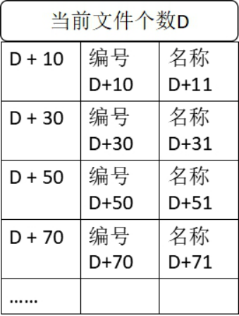
图6 sequence of file information arrangement
1.1.2. Attention:
For high-speed pulse output, it is designed for external high-speed devices. To count the pulses, only the high-speed pulse input counter can be used, and internal counters or Y edge changes cannot be used for counting. When used as a high-speed output, it cannot be used as a regular output port;
The OFF time of transistors has the characteristic of being prolonged under light loads. So, when responsiveness is required, please design a load resistor to increase the load current when the load is lighter;
The pulse accumulation count registers (D8140~D8146) are important registers that can be read and written. When a new value is written, the count will be added or subtracted based on the new value;
Due to the directional output of the pulse in this instruction, the pulse accumulation count registers (D8140~D8146) count according to the direction;
When outputting high-speed pulses, the values in the pulse accumulation count registers (D8140~D8146) are discontinuous and constantly changing. When used for judgment, please use size comparison instead of equal judgment;
Do not set the acceleration and deceleration time too small, otherwise there will be no acceleration and deceleration effect;
The pulse is sending a flag bit, such as M8134, which only represents whether Y0 is outputting a pulse. If it is necessary to detect whether a pulse is being sent in plane system 1, use M8144. When running the interpolation command, if any axis in the plane system sends a pulse, this bit will be ON;
The speed and XY axis offset of the HMIPLINE instruction must be assigned using the MOVF instruction;
The size of a single. ssd file should not exceed 32KB;
The HMIPLINE instruction cannot be used simultaneously by multiple instructions, and only one HMIPLINE instruction can be used at a time;
When the number of graphics downloaded using HMI exceeds 20, the last graphic will be automatically overwritten.
If the frequency of multiple pulse pulses exceeds 200K, a pull-up resistor needs to be added to the pulse output port to ensure that the pulse waveform is not distorted. The pull-up voltage is 24V, and the recommended pull-up resistor is 1K.