1. Multi segment interpolation POLYLINEI/POLYLINEF
1. Multi segment interpolation POLYLINEI/POLYLINEF
| Corresponding Command | Annotation/Description | Parameters |
|---|---|---|
| POLYLINE/POLYLINE | Multi segment interpolation instruction | Plane system number |
| Is the parameter mapped to the D register | ||
| Initial address of D register | ||
| Line type | ||
| Parameter settings for line/arc interpolation |
1.1. Instruction Description
This instruction is only applicable to some PLC models;
The PLC high-speed pulse output port is Y0~Y3, with a pulse frequency range of 0~200KHz;
POLYLINE/POLYLINE are integer parameter instructions and floating-point parameter instructions, respectively, corresponding to pulse pls and millimeter mm units;
The function of this instruction is to complete the combination motion of straight lines and arcs. Draw the line segments in sequence according to the line segment sequence box on the left. If the adjacent two line segments are in a collinear or tangential transition, there will be no acceleration or deceleration pauses at the intersection, and a smooth transition. Otherwise, there will be acceleration or deceleration pauses. Please refer to the LINEI/LINEF and ARCI/ARCF instructions for the parameter settings of its straight lines and arcs;
If the speed entered by the user is negative, its absolute value will be taken as the valid value;
The main purpose of mapping POLYLINE parameters to the D register is to dynamically control the parameters. The original parameters can be modified in the D register or parameters can be added later to achieve the purpose of adding line segments to the modified position. In addition, modifying the D register value of speed during motion can achieve real-time speed control. If only D control is selected, the user does not need to input any position or velocity parameters in the POLYLINE instruction, and the motion is directly determined by the parameter sequence of the assigned D register. The last segment needs to fill the control parameter with 0XFF as the end flag, otherwise an error will be reported. Please refer to the following paragraph for specific parameter storage rules.
1.1.1. Instruction usage instructions:
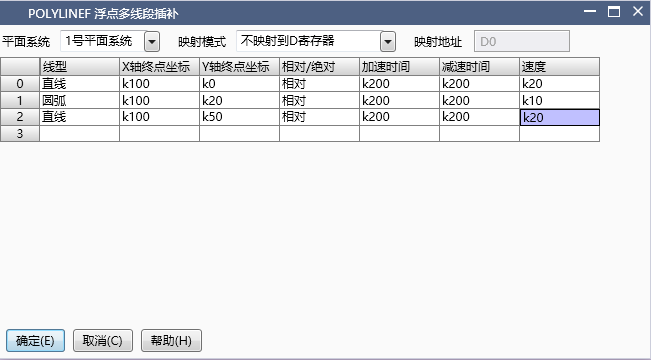
图1 POLYLINEF Instruction Diagram
1) Firstly, select the plane number. For plane settings, please refer to "Plane System Settings". If the plane system is not enabled, it will not function properly;
2) The unit of this instruction parameter can be millimeters (mm) or pulses (pls), corresponding to POLYLINEF and POLYLINEI instructions, respectively. It is recommended that users use mm as the unit, with parameters that are in line with reality and do not require conversion, making it less prone to errors;
3) Right click the mouse in the left line segment sequence box to select add, insert, delete, or move elements;
4) Please refer to the LINEI/LINEF and ARCI/ARCF instructions for parameter settings of straight lines and arcs;
5) Both position and velocity parameters can be input as K/D type data, which are non adjustable and adjustable, respectively. When the speed parameter is input as D, the value in the D register changes, and the speed is adjusted in real time accordingly. During acceleration and deceleration, the speed adjustment will not respond immediately when the speed parameter is adjusted, and the speed change will be adjusted immediately after the acceleration and deceleration. Emphasize that when using MOV class instructions to assign position and velocity parameters, whether to use MOVD or MOVF depends on the POLYLINEI and POLYLINEF types of the selected instructions. POLYLINEI is an integer instruction corresponding to the pulse unit pls, and its parameters need to be assigned using MOVD. POLYLINEF is a floating-point instruction corresponding to the millimeter millimeter unit, and its parameters need to be assigned using MOVF. The unit of acceleration and deceleration time parameter is ms, which is a 16 bit integer and requires the use of MOV instruction, regardless of the type of interpolation instruction;
6) Mapping data to the D register, as shown in the figure "Mapping to the D register", involves storing the set position and velocity parameters in a specific order in the D register when the instruction is enabled, and changing the mapping path of the position and velocity parameters. To modify the position or real-time speed regulation, the address parameters newly mapped to the D register must be adjusted. The parameter storage rule for mapping is shown in the figure "Parameter Storage Rule for Mapping Parameters to the D Register", which loops in the order of line segments. After selecting the mapping, the D register address mapped to will be displayed below the parameters. Users can change the parameters and adjust the shape of the graph before executing the line segment. However, it should be noted that the execution of line segments is forward-looking. The last segment of the currently executing line segment has already been processed. If you need to change the shape of the graphic element, you must start from the last two segments of the currently executing line segment. Otherwise, forward-looking errors may occur, resulting in errors or running confusion. This feature is only applicable when minor modifications to the shape are required.
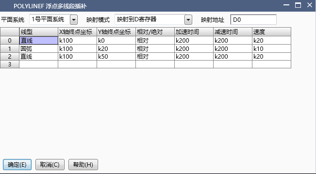
图2 POLYLINEF instruction diagram1
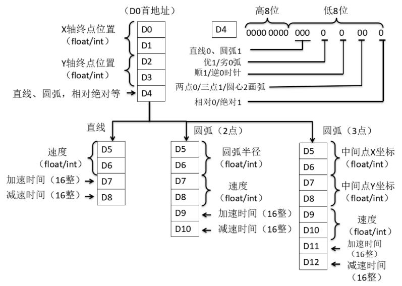
图3 POLYLINEF instruction diagram2
7) Only controlled by the D register, when this mode is selected, the parameters of straight lines and arcs are only controlled by the D register. Data cannot be filled in the instruction, and the data already filled in is invalid. The data storage rule is shown in the figure "Only D register control parameter storage rule". The line segment parameters are cycled according to the settings. It should be noted that only D control has a global velocity. If the velocity in other line segments is the same as the global velocity, it can be omitted. If they are not the same, the velocity parameter of that line segment can be added separately at the end of the line segment data (the red part in the figure, if not selected, the parameter of the immediately following segment will not be included), and the control bit "individual velocity" is set to 1. When adjusting real-time speed, adjusting the global speed does not affect line segments with individual speeds. If speed adjustment is required for line segments with individual speeds, the values in their individual speed addresses need to be adjusted. This function is suitable for batch modification of graphic shapes.
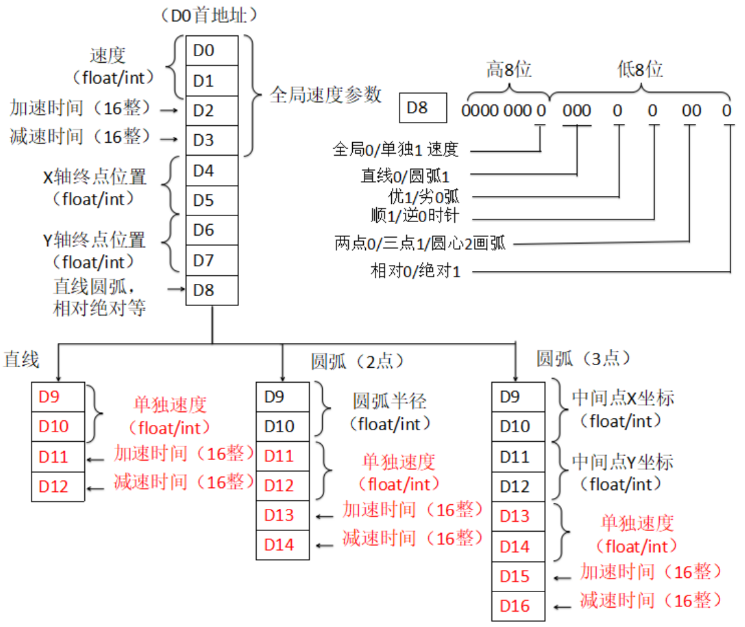
图4 POLYLINEF instruction diagram3
| register | Pulse port |
|---|---|
| M8134 | Y000 |
| M8135 | Y001 |
| M8136 | Y002 |
| M8137 | Y003 |
| register | Pulse port |
|---|---|
| M8138 | Y004 |
| M8139 | Y005 |
| M8140 | Y006 |
| M8141 | Y007 |
| M8142 | Y010 |
| M8143 | Y011 |
| register | Pulse port |
|---|---|
| M8144 | Y000 |
| M8145 | Y001 |
| M8146 | Y002 |
| M8147 | Y003 |
| register | Pulse port |
|---|---|
| D8140(D8141) | Y000 |
| D8142(D8143) | Y001 |
| D8144(D8145) | Y002 |
| D8146(D8147) | Y003 |
| register | Pulse port |
|---|---|
| D8148(D8149) | Y004 |
| D8150(D8151) | Y005 |
| D8152(D8153) | Y006 |
| D8154(D8155) | Y007 |
| D8156(D8157) | Y010 |
| D8158(D8159) | Y011 |
| register | Pulse port |
|---|---|
| D8124 | Y000 |
| D8125 | Y001 |
| D8126 | Y002 |
| D8127 | Y003 |
| register | Pulse port |
|---|---|
| D8128 | Y004 |
| D8129 | Y005 |
| D8130 | Y006 |
| D8131 | Y007 |
| D8132 | Y010 |
| D8133 | Y011 |
| register | Pulse port |
|---|---|
| D8108 | Y000 |
| D8109 | Y001 |
| D8110 | Y002 |
| D8111 | Y003 |
| register | Pulse port |
|---|---|
| D8112 | Y004 |
| D8113 | Y005 |
| D8114 | Y006 |
| D8115 | Y007 |
| D8116 | Y010 |
| D8117 | Y011 |
1.1.2. Attention:
For high-speed pulse output, it is designed for external high-speed devices. To count the pulses, only the high-speed pulse input counter can be used, and internal counters or Y edge changes cannot be used for counting. When used as a high-speed output, it cannot be used as a regular output port;
The OFF time of transistors has the characteristic of being prolonged under light loads. So, when responsiveness is required, please design a load resistor to increase the load current when the load is lighter;
The pulse accumulation count registers (D8140~D8158) are important registers that can be read and written. When a new value is written, the count will be added or subtracted based on the new value;
Due to the directional output of the pulse in this instruction, the pulse accumulation count registers (D8140~D8158) count according to the direction;
When outputting high-speed pulses, the values in the pulse accumulation count registers (D8140~D8158) are discontinuous and constantly changing. When used for judgment, please use size comparison instead of equal judgment;
Do not set the acceleration and deceleration time too small, otherwise there will be no acceleration and deceleration effect;
When the unit is set to pulse pls, the speed unit is pls/s. If the X-axis and Y-axis pulse equivalents set by the planar system are not equal, the true speed is calculated by default based on the X-axis pulse equivalent;
The pulse is sending a flag bit. For example, M8134 only represents whether Y0 is outputting a pulse. If it is necessary to detect whether a pulse is being sent in plane system 1, use M8144. When running the interpolation command, if any axis in the plane system sends a pulse, this bit will be ON;
When the pulse command is used to output port Y, the Y port cannot be used for other purposes, that is, ordinary commands cannot perform ON or OFF operations on the Y port anymore.
1.2. The valid operands of instructions
1.2.1. integer instruction(POLYLINEI)
| Input/Output | Data Type | operand | Description |
|---|---|---|---|
| ID | 16 bit unsigned integer | K/H | Number |
1.2.2. Float instruction(POLYLINEF)
| Input/Output | Data Type | operand | Description |
|---|---|---|---|
| ID | 16 bit unsigned integer | K/H | Number |
1.3. Example
Command table:
NETWORK 000
LD M40
MPS
MEP
MOVF K20 D2000
MPP
POLYLINEF K1
NETWORK 001
LD M8144
MPS
MEP
SET M500 K1
MPP
MEF
RST M500 K1
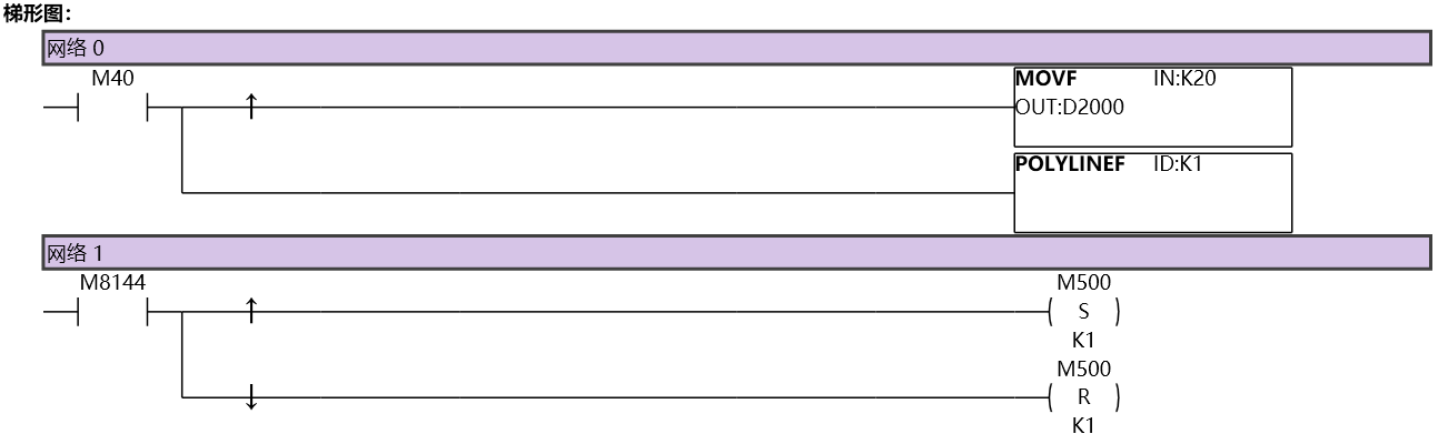
图5 POLYLINEI11
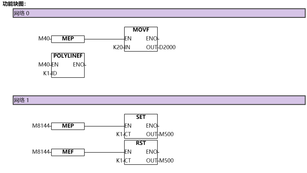
图6 POLYLINEI12