1. Pulse Width Modulation (Periodic) PWMS
1. Pulse Width Modulation (Periodic) PWMS
1.1. Instruction Description
This instruction is only applicable to some PLC models.
Pulse width modulation (periodic) generates a pulse output with a variable period and variable pulse width time.
When the input terminal is turned on, the pulse is immediately outputted continuously with the set cycle and pulse width time. During the output process, the cycle and pulse width time can be modified and take effect immediately until the prerequisite for the pulse command is disconnected.
The PWMS instruction can choose a time unit of ms or us. When the time unit is ms, the cycle setting range is 2-65535ms, and the pulse width time range is 0-65535ms; When the time unit is us, the setting range of the cycle is 5-65535us, and the pulse width time range is 0-65535us. Due to waveform distortion in high-frequency pulses, the PLC automatically limits the pulse width when the time unit is in microseconds. If the pulse width time is equal to microseconds (or the time obtained by subtracting the pulse width from the cycle is equal to microseconds), the pulse width time (or the time obtained by subtracting the pulse width from the cycle) is forcibly changed to 2us to ensure the waveform of high and low levels as much as possible.
The PWMS instruction provides the function of changing the output sequence of voltage levels, which can be manually set within a pulse cycle to output the effective or invalid voltage level first. When M8062 is OFF, the invalid level comes first and the effective level comes second; When M8062 is ON, the effective level comes first and the ineffective level comes second. Note: The M8062 level output sequence needs to be modified before enabling the PWMS instruction. If the M8062 state is modified during the PWM output period, the order of level output will not change.
For 16 point transistor type PLCs, Y0~Y1 are high-speed pulse output ports, and for 32/50/66 point transistor type PLCs, Y0~Y3 are high-speed pulse output ports; Relay type PLCs do not have high-speed pulse function, and the maximum output frequency of the output port is determined by the closing time of the relay. For multi pulse series PLCs, their high-speed pulse output ports are Y0~Y7 and Y10~Y11.
| register | Pulse port |
|---|---|
| D8140(D8141) | Y000 |
| D8142(D8143) | Y001 |
| D8144(D8145) | Y002 |
| D8146(D8147) | Y003 |
| register | Pulse port |
|---|---|
| D8148(D8149) | Y004 |
| D8150(D8151) | Y005 |
| D8152(D8153) | Y006 |
| D8154(D8155) | Y007 |
| D8156(D8157) | Y010 |
| D8158(D8159) | Y011 |
| register | Pulse port |
|---|---|
| M8118 | Y000 |
| M8119 | Y001 |
| M8120 | Y002 |
| M8121 | Y003 |
| register | Pulse port |
|---|---|
| M8122 | Y004 |
| M8123 | Y005 |
| M8124 | Y006 |
| M8125 | Y007 |
| M8126 | Y010 |
| M8127 | Y011 |
1.1.1. Attention:
The PWM cycle and pulse width time are 16 bit positive integers;
For high-speed pulse output, it is designed for external high-speed devices. To count the pulses, only the high-speed pulse input counter can be used, and internal counters cannot be used, nor can Y edge changes be used for counting;
The OFF time of transistors has the characteristic of being prolonged under light loads. So, when responsiveness is required, please design a load resistor to increase the load current when the load is lighter;
The PWMS instruction does not have a pulse accumulation counting function, and the values of pulse counting registers such as D8140 and D8142 will not increase when outputting pulses;
When the frequency is too high, there may be waveform distortion. To achieve precise pulse width control, the pulse frequency should not be too high.
When the pulse command is used to output port Y, the Y port cannot be used for other purposes, that is, ordinary commands cannot perform ON or OFF operations on the Y port anymore.
If the frequency of multiple pulse pulses exceeds 200K, a pull-up resistor needs to be added to the pulse output port to ensure that the pulse waveform is not distorted. The pull-up voltage is 24V, and it is recommended to use a pull-up resistor of 1K.
1.2. The valid operands of the instruction
| Input/Output | Data Type | operand | Description |
|---|---|---|---|
| U | 16 bit unsigned integer | K/H | Time unit |
| P | 16 bit unsigned integer | D/CV/TV/AI/AO/K/H/V/Z/FD, bit composite word (X/Y/M/C/T/S), local variable (LW) | period |
| DP | 16 bit unsigned integer | D/CV/TV/AI/AO/K/H/V/Z/FD, bit composite word (X/Y/M/C/T/S), local variable (LW) | pulse width time |
| OUT | ON/OFF | Y | Pulse |
1.2.1. Attention:
Time unit: The time unit for subsequent parameters can only be filled in as a constant. K0: Unit is ms; K1: The unit is us.
Pulse width time: The set pulse width time cannot exceed the duration of the cycle.
1.3. Example
Command table:
NETWORK 000
LD M0
PWMS K0 D0 D1 Y000 // When M0 is' 1 ', the Y000 outputs a pulse with a period of D0 (ms) and a pulse width time of D1 (ms).
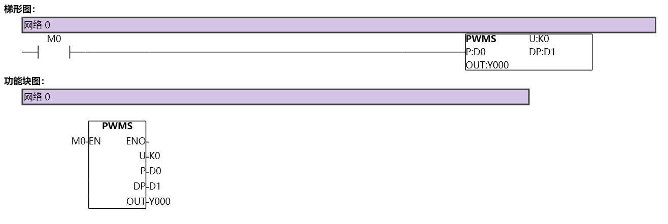
图1 PWMS