1. Graphic import (batch import) command BLOCK
1. Graphic import (batch import) command BLOCK
1.1. Instruction description
This instruction is only valid for some models (SamSoar software "tool" "Get PLC version information" obtains firmware version information starting with "g" and version number higher than g210), this instruction is invalid for other PLCs;
FGm_ The 64MT-AC high-speed pulse output ports are Y0~Y7, Y10~Y11, with a pulse frequency range of 0~500KHz. FGRS&# 95; C8X8T high-speed pulse output port is Y0~Y3, with a pulse frequency range of 0~200KHz;
The function of this instruction is to complete the drawing of imported graphics in a specified plane system;
Currently, importing graphics only supports graphics composed of line and arc commands in AutoCAD, and only supports importing saved DXF files.
1.1.1. Instruction usage instructions
Firstly, in AutoCAD software, use the line and arc commands to draw design graphics. It should be noted that the size of the plane system needs to be determined, and the drawn graphics cannot exceed the boundaries of the plane system. The drawing method for importing graphics is absolute coordinate drawing, so the origin of the plane system needs to coincide with the origin of the world coordinate system in AutoCAD. The dimensions in AutoCAD are all in mm units. After drawing, confirm that all line segments in the graphics are the ones that need to be drawn, and save them as 2004dxf;
Build a flat system;
The click path for importing graphics is: Main Menu ->Pulse ->Graphics Import;
After completing the import, select the plane system where the graphic is located and set the speed parameter;
Create a BLOCK command in the ladder diagram, select the shape to be drawn, and fill in the control bits. During the drawing process, some shapes cannot be completed in one stroke, so transition lines are needed between the graphic elements. These transition lines do not need to be drawn and are called dashed lines. The ones that need to be drawn are called solid lines. The flag bit is used to distinguish between solid and dashed lines. When it is a dashed line, the flag bit is 0, and when it is a solid line, the flag bit is 1;
| Register Pulse | pulse output |
|---|---|
| M8134 | Y000 |
| M8135 | Y001 |
| M8136 | Y002 |
| M8137 | Y003 |
| Register Pulse | pulse output |
|---|---|
| M8138 | Y004 |
| M8139 | Y005 |
| M8140 | Y006 |
| M8141 | Y007 |
| M8142 | Y010 |
| M8143 | Y011 |
| Register Pulse | pulse output |
|---|---|
| M8144 | Y000 |
| M8145 | Y001 |
| M8146 | Y002 |
| M8147 | Y003 |
| Register Pulse | pulse output |
|---|---|
| D8140(D8141) | Y000 |
| D8142(D8143) | Y001 |
| D8144(D8145) | Y002 |
| D8146(D8147) | Y003 |
| Register Pulse | pulse output |
|---|---|
| D8148(D8149) | Y004 |
| D8150(D8151) | Y005 |
| D8152(D8153) | Y006 |
| D8154(D8155) | Y007 |
| D8156(D8157) | Y010 |
| D8158(D8159) | Y011 |
| Register Pulse | pulse output |
|---|---|
| D8124 | Y000 |
| D8125 | Y001 |
| D8126 | Y002 |
| D8127 | Y003 |
| Register Pulse | pulse output |
|---|---|
| D8128 | Y004 |
| D8129 | Y005 |
| D8130 | Y006 |
| D8131 | Y007 |
| D8132 | Y010 |
| D8133 | Y011 |
| Register Pulse | pulse output |
|---|---|
| D8108 | Y000 |
| D8109 | Y001 |
| D8110 | Y002 |
| D8111 | Y003 |
| Register Pulse | pulse output |
|---|---|
| D8112 | Y004 |
| D8113 | Y005 |
| D8114 | Y006 |
| D8115 | Y007 |
| D8116 | Y010 |
| D8117 | Y011 |
1.1.2. Attention:
For high-speed pulse output, it is designed for external high-speed devices. To count the pulses, only the high-speed pulse input counter can be used, and internal counters or Y edge changes cannot be used for counting. When used as a high-speed output, it cannot be used as a regular output port;
The OFF time of transistors has the characteristic of being prolonged under light loads. So, when responsiveness is required, please design a load resistor to increase the load current when the load is lighter;
The pulse accumulation count registers (D8140~D8146) are important registers that can be read and written. When a new value is written, the count will be added or subtracted based on the new value;
Due to the directional output of the pulse in this instruction, the pulse accumulation count registers (D8140~D8146) count according to the direction;
When outputting high-speed pulses, the values in the pulse accumulation count registers (D8140~D8146) are discontinuous and constantly changing. When used for judgment, please use size comparison instead of equal judgment;
Do not set the acceleration and deceleration time too small, otherwise there will be no acceleration and deceleration effect;
The pulse is sending a flag bit, such as M8134, which only represents whether Y0 is outputting a pulse. If it is necessary to detect whether a pulse is being sent in plane system 1, use M8144. When running the interpolation command, if any axis in the plane system sends a pulse, this bit will be ON;
The data type of speed must be floating-point numbers, independent of unit settings. Therefore, when using the D register to assign speed for real-time speed regulation, the MOVF instruction must be used to assign speed;
If the speed parameter is not valid when drawing graphics, it will automatically adjust the speed, and the speed will decrease according to the shape of the graphics;
- The size of imported graphic data should not be too large, otherwise it cannot be downloaded;
When the pulse command is used to output port Y, the Y port cannot be used for other purposes, that is, ordinary commands cannot perform ON or OFF operations on the Y port anymore.
If the frequency of multiple pulse pulses exceeds 200K, a pull-up resistor needs to be added to the pulse output port to ensure that the pulse waveform is not distorted. The pull-up voltage is 24V, and the recommended pull-up resistor is 1K.
1.2. The valid operands of the instruction
| Input/Output | Data Type | operand | Description |
|---|---|---|---|
| NAME | Text | Name | |
| OUT | ON/OFF | Y/M | Pulse |
1.3. Example
Draw the following graph with control bit Y6. Refer to Figure 1 for the graphic import interface, import the lufei_A4.dxf file, and set the plane system, speed, and acceleration/deceleration time. Use the command BLOCK to select the file and set the real virtual control bit Y6.
Command table:
NETWORK 000
LD M30
BLOCK Lufei_A4 Y006
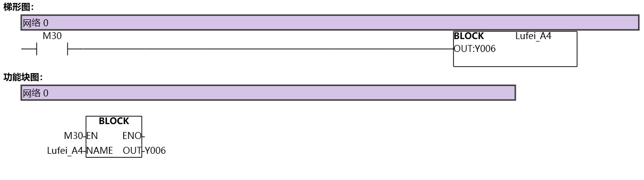
图1 BLOCK