1. Near Origin Return to Origin ZRN
1. Near Origin Return to Origin ZRN
1.1. Instruction Description
When the input terminal is turned on, the return to origin ZRN command first sets the output pulse at the return speed. When the near point signal is set, it immediately decelerates from the return speed to the crawling speed set output pulse within a certain time. When the near point signal is reset, the pulse transmission stops. When the input terminal is turned off, pulse transmission immediately stops.
| register | Pulse port |
|---|---|
| M8134 | Y000 |
| M8135 | Y001 |
| M8136 | Y002 |
| M8137 | Y003 |
| register | Pulse port |
|---|---|
| M8138 | Y004 |
| M8139 | Y005 |
| M8140 | Y006 |
| M8141 | Y007 |
| M8142 | Y010 |
| M8143 | Y011 |
| register | Pulse port |
|---|---|
| D8140(D8141) | Y000 |
| D8142(D8143) | Y001 |
| D8144(D8145) | Y002 |
| D8146(D8147) | Y003 |
| register | Pulse port |
|---|---|
| D8148(D8149) | Y004 |
| D8150(D8151) | Y005 |
| D8152(D8153) | Y006 |
| D8154(D8155) | Y007 |
| D8156(D8157) | Y010 |
| D8158(D8159) | Y011 |
1.1.1. Attention:
After completing the return to origin action using this instruction, the pulse accumulation registers (D8140~D8158) of the corresponding output ports will automatically reset to zero, serving as the origin;
When the pulse command is used to output port Y, the Y port cannot be used for other purposes, that is, ordinary commands cannot perform ON or OFF operations on the Y port anymore;
For the ZRN directional return to origin command, if negative directional return to origin is required, both the regression speed and crawling speed must be set to negative values;
If the frequency of multiple pulse pulses exceeds 200K, a pull-up resistor needs to be added to the pulse output port to ensure that the pulse waveform is not distorted. The pull-up voltage is 24V, and the recommended pull-up resistor is 1K.
1.2. The valid operands of instruction
| Input/Output | Data Type | operand | Description |
|---|---|---|---|
| HV | 32-bit integer | D/CV/K/H/FD, bit composite word (X/Y/M/C/T/S), local variable (LD) | regression speed |
| LV | 32-bit integer | D/CV/K/H/FD, bit composite word (X/Y/M/C/T/S), local variable (LD) | crawling speed |
| AC | 16 bit unsigned integer | D/CV/TV/AI/AO/K/H/V/Z/FD, bit composite word (X/Y/M/C/T/S), local variable (LW) | acceleration time |
| DC | 16 bit unsigned integer | D/CV/TV/AI/AO/K/H/V/Z/FD, bit composite word (X/Y/M/C/T/S), local variable (LW) | deceleration time |
| SIG | ON/OFF | X/M | Near Point Signal |
| OUT | ON/OFF | Y | Pulse |
| DIR | ON/OFF | Y | Direction |
1.3. Example
Command table:
NETWORK 000
LDP M8151
MOVD K100000 D0//Regression speed, pulse frequency 100KHz
MOVD K5000 D2//Crawling speed, pulse frequency 5KHz
MOV K100 D4//Acceleration and deceleration time 100ms
NETWORK 001
LD M0
ZRN D0 D2 D4 X0 Y0 Y4//When M0 is' 1 ', a pulse with D0 frequency is output first at Y0. When a rising edge is received at X0, the output frequency of Y0 changes the speed from D0 to D2 within D4 time. If a falling edge is received at X0, the pulse transmission will be stopped directly
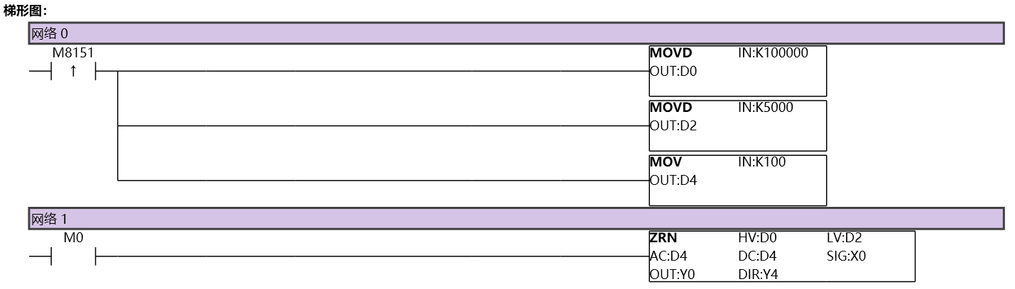
图1 ZRN11
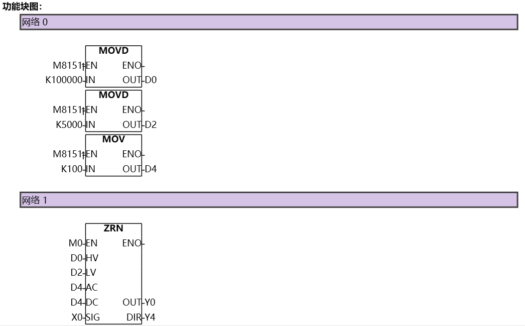
图2 ZRN12