1. Multi segment pulse output PLSR/PLSA/EPLSR
1. Multi segment pulse output PLSR/PLSA/EPLSR
1.1. Instruction Description
The PLSR/PLSA/EPLSR instruction for multi segment pulse output can be used to achieve multi segment pulse output at a preset frequency and number of pulses. The output conversion between different segments should be completed within the preset acceleration and deceleration time. When the input terminal is turned on, immediately output pulses from the starting frequency of the first segment, accelerate to the preset frequency of the first segment within the predetermined acceleration and deceleration time, and when the number of output pulses reaches the preset number of output pulses of the first segment; Accelerate and decelerate to the second preset frequency within the predetermined acceleration and deceleration time. When the number of output pulses reaches the second preset output pulse, execute according to the third preset value until the number of segment pulses is set to 0 or the frequency is set to 0, indicating the end of the segment, and the pulse output stops.
The set values for multi segment frequency and pulse number are set in the pulse parameter address. A region starting from Dn.
The 32-bit PLSR/PLSA/EPLSR command can output a frequency range of 0Hz~200KHz and a pulse range of K0~K2147483647. The acceleration and deceleration time of each section of PLSR/PLSA is the same, while the acceleration and deceleration time of each section of EPLSR can be set separately, and the acceleration and deceleration time of the last section can be set separately.
每段设定脉冲频率,脉冲个数和加减速时间满足关系式:(起始频率Hz + 结束频率Hz)×( 加减速时间ms÷1000) <= 脉冲个数 × 2。
- 单向相对位置多段脉冲输出PLSR脉冲方向Y只由第一段设定的脉冲个数或者脉冲频率的正负决定,当第一段设定的脉冲个数或者频率为正数时,为正方向,Y输出为ON;当设定的脉冲个数或者频率为负数时,为负方向,Y输出为OFF。对于绝对定位指令PLSA,脉冲个数代表其绝对位置,各段的正负可不相同,会自动变换方向。
For bidirectional relative position multi segment pulse output EPLSR pulse direction, the direction is determined by the positive or negative number of pulses in each segment. When the positive or negative number of pulses in this segment changes relative to the previous segment, the previous segment will slow down to 0, and this segment will accelerate in reverse from 0 to the frequency of this segment. The direction can be automatically changed based on the positive or negative number of pulses in each segment, and the acceleration and deceleration times can be set separately for the last segment.
The special function register M8068 is used for directional polarity control. The default pulse direction output port is ON, which indicates the positive direction, and OFF, which indicates the negative direction. If M8068 is set to ON, the polarity of the directional output of all pulse commands will be reversed, with OFF indicating positive direction and ON indicating negative direction.
For 16 point transistor type PLCs, Y0~Y1 are high-speed pulse output ports, and for 32/50/66 point transistor type PLCs, Y0~Y3 are high-speed pulse output ports; Relay type PLCs do not have high-speed pulse function, and the maximum output frequency of the output port is determined by the closing time of the relay. For multi pulse series PLCs, their high-speed pulse output ports are Y0~Y7 and Y10~Y11.
When the special function register M8069 is ON, the acceleration and deceleration of all pulse instructions are S-shaped, and when it is OFF, they are trapezoidal.
During the process of sending multiple pulse segments, when the pulse has not yet been sent to that segment, the parameters of that segment can be changed arbitrarily. When running to this segment, it will run with the new parameters. But when the pulse is sent to the previous segment of the pulse, do not change the parameters of that segment to 0, otherwise it will cause a sudden frequency change in the final segment. Similarly, the D register, which was originally the end flag, can be modified to include parameterized pulse segments to achieve the function of adding pulse segments;
1.1.1. The data format of 32-bit instruction:
Taking D0 (doubleword) as the starting address, D0 (doubleword) sets the highest frequency of the first segment pulse, D2 (doubleword) sets the number (position) of the first segment pulse, D4 (doubleword) sets the highest frequency of the second segment pulse, D6 (doubleword) sets the number (position) of the second segment pulse,... Dn sets the highest frequency of the (n+4)/4th segment pulse, Dn+2 sets the number of (n+4)/4th segment pulses to 0, indicating the end of the segment.
1.1.2. The data format of 32-bit instruction:
Taking D0 (doubleword) as the starting address, D0 (doubleword) sets the first acceleration time, D2 (doubleword) sets the highest frequency of the first pulse, D4 (doubleword) sets the number of first pulses, D6 (doubleword) sets the second acceleration time,..., Dn sets the (n+6)/6th acceleration time, Dn+2 sets the highest frequency of the (n+6)/6th segment, Dn+4 sets the number of pulses of the (n+6)/6th segment, Dn+6 sets the deceleration time of the (n+6)/6th segment, Dn+10 sets the pulse frequency of the (n+6)/6th segment, and... Dn+12 sets the number of pulses in the (n+6)/6th segment to 0, indicating the end of the segment. When the number of pulses in a certain segment is set to -1, it means that the pulse in that segment will continue to be sent until it encounters the PLSNNEXT command to switch segments.
| register | Pulse port |
|---|---|
| M8134 | Y000 |
| M8135 | Y001 |
| M8136 | Y002 |
| M8137 | Y003 |
| register | Pulse port |
|---|---|
| M8138 | Y004 |
| M8139 | Y005 |
| M8140 | Y006 |
| M8141 | Y007 |
| M8142 | Y010 |
| M8143 | Y011 |
| register | Pulse port |
|---|---|
| M8102 | Y000 |
| M8103 | Y001 |
| M8104 | Y002 |
| M8105 | Y003 |
| register | Pulse port |
|---|---|
| M8106 | Y004 |
| M8107 | Y005 |
| M8108 | Y006 |
| M8109 | Y007 |
| M8110 | Y010 |
| M8111 | Y011 |
| register | Pulse port |
|---|---|
| D8140(D8141) | Y000 |
| D8142(D8143) | Y001 |
| D8144(D8145) | Y002 |
| D8146(D8147) | Y003 |
| register | Pulse port |
|---|---|
| D8148(D8149) | Y004 |
| D8150(D8151) | Y005 |
| D8152(D8153) | Y006 |
| D8154(D8155) | Y007 |
| D8156(D8157) | Y010 |
| D8158(D8159) | Y011 |
| register | Pulse port |
|---|---|
| M8118 | Y000 |
| M8119 | Y001 |
| M8120 | Y002 |
| M8121 | Y003 |
| register | Pulse port |
|---|---|
| M8122 | Y004 |
| M8123 | Y005 |
| M8124 | Y006 |
| M8125 | Y007 |
| M8126 | Y010 |
| M8127 | Y011 |
1.1.3. Attention:
Each output frequency of PLSR/PLSA/EPLSR is a 32-bit positive integer, occupying two consecutive D registers;
For high-speed pulse output, it is designed for external high-speed devices. To count the pulses, only the high-speed pulse input counter can be used, and internal counters cannot be used, nor can Y edge changes be used for counting;
The OFF time of transistors has the characteristic of being prolonged under light loads. So, when responsiveness is required, please design a load resistor to increase the load current when the load is lighter;
For the pulse output Y0, the number of pulses is accumulated in register D8140 (D8141), where D8141 stores the high 16 bits and D8140 stores the low 16 bits;
The pulse accumulation count registers (D8140~D8158) are important registers that can be read and written. When a new value is written, the count will be added or subtracted based on the new value;
Due to the directional output of the pulse in this instruction, the pulse accumulation counting registers (D8140~D8158) count according to the direction;
When outputting high-speed pulses, the values in the pulse accumulation count registers (D8140~D8158) are discontinuous and constantly changing. When used for judgment, please use size comparison instead of equal judgment;
When it is an n-segment pulse, the addresses of the pulse frequency and number of pulses in each segment of the first segment, second segment, third segment, etc. must be consecutive in sequence, and the address of the pulse frequency and number of pulses in the (n+1) - th segment must be 0 to determine whether the pulse segment has ended; The address of acceleration and deceleration time cannot follow immediately after the nth paragraph;
The multi pulse and basic PLSR instructions only have a -1 continuous transmission function in the first segment, and only the number of pulses and frequency in the first segment determine the direction of the entire process. The following segments will be sent with absolute values.
The EPLSR instruction does not have a continuous sending function. A pulse count of -1 indicates sending a pulse in reverse, and the direction of each segment is determined by the number of pulses. Negative frequency values will be treated as absolute values.
The current pulse segment (D8124-D8133) is only recorded during the pulse transmission process and automatically resets to zero when the command fails.
When the pulse command is used to output port Y, the Y port cannot be used for other purposes, that is, ordinary commands cannot perform ON or OFF operations on the Y port anymore.
If the frequency of multiple pulse pulses exceeds 200K, a pull-up resistor needs to be added to the pulse output port to ensure that the pulse waveform is not distorted. The pull-up voltage is 24V, and it is recommended to use a pull-up resistor of 1K.
1.2. The valid operands of the instruction
1.2.1. Bidirectional relative position multi segment pulse output (PLSR)
| Input/Output | Data Type | operand | Description |
|---|---|---|---|
| D | 32-bit integer | D | Address |
| T | 16 bit unsigned integer | D/CV/TV/AI/AO/K/H/V/Z/FD, bit composite word (X/Y/M/C/T/S), local variable (LW) | acceleration/deceleration time |
| OUT | ON/OFF | Y | Pulse |
| DIR | ON/OFF | Y | Direction |
1.2.2. Bidirectional absolute position multi segment pulse output(PLSA)
| Input/Output | Data Type | operand | Description |
|---|---|---|---|
| D | 32-bit integer | D | Address |
| T | 16 bit unsigned integer | D/CV/TV/AI/AO/K/H/V/Z/FD, bit composite word (X/Y/M/C/T/S), local variable (LW) | acceleration/deceleration time |
| OUT | ON/OFF | Y | Pulse |
| DIR | ON/OFF | Y | Direction |
1.2.3. Multi stage variable speed pulse output for relative position(EPLSR)
| Input/Output | Data Type | operand | Description |
|---|---|---|---|
| D | 32-bit integer | D | Address |
| OUT | ON/OFF | Y | Pulse |
| DIR | ON/OFF | Y | Direction |
1.3. Example
Command table:
NETWORK 000
LDP M8151
MOVD K100000 D0//The first segment frequency is 100KHz and stored in D0D1
MOVD K200000 D2//Number of pulses in the first segment 2000000 stored in D2D3
MOVD K200000 D4//Second segment frequency 200KHz stored in D4D5
MOVD K300000 D6//The second segment has 300000 pulses stored in D6D7
FMOVD K0 D8 K2//End flag frequency 0 is stored in D8D9, pulse number 0 is stored in D10D11
NETWORK 001
LD M0
PLSR D0 K100 Y000 Y004//When M0 is set, the PLSR instruction starts working
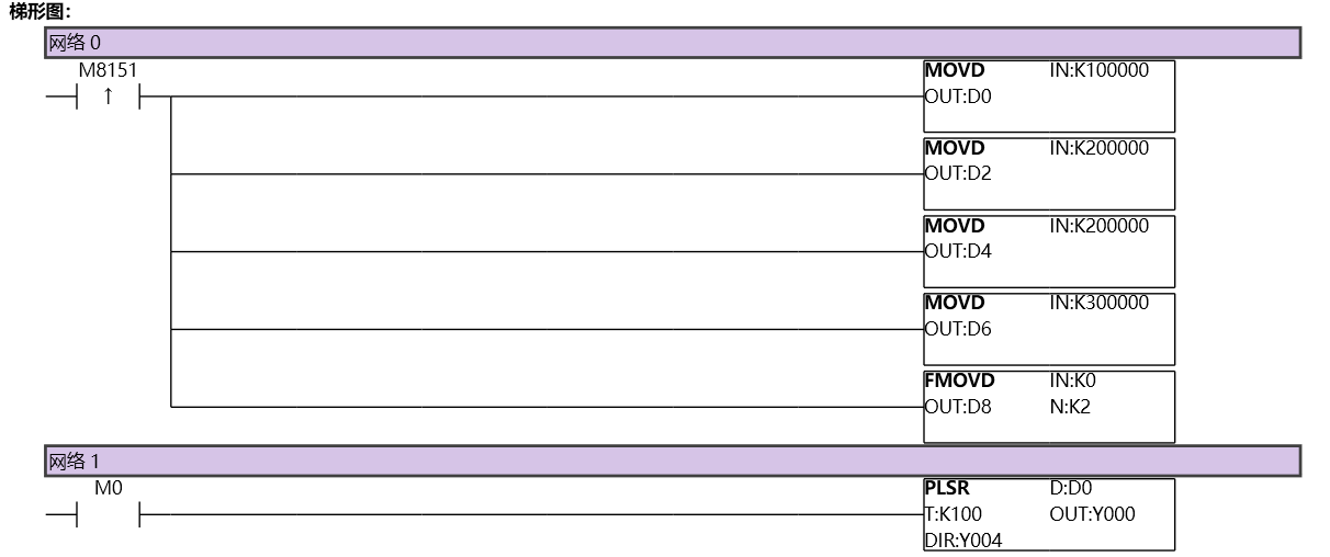
图1 PLSR11
图2 PLSR12
1.4. Run the specified step size after detecting the signal
After detecting the X0 signal, run 50000 pulses to stop pulse transmission. The program is as follows. Firstly, send pulses at a frequency of 50KHz, with a pulse count of -1 indicating continuous pulse transmission. When X0 detects a rising edge signal, it performs PLSNNEXT segment switching and enters the next segment, with a pulse frequency of 20KHz and 50000 pulses in the next segment. During the first stage of operation, the value of 50000 pulses for the second stage can be modified. If the pulse quantity for the second stage is unknown before starting the first stage, a parameter can be set arbitrarily (cannot be 0) and modified before switching stages.
Command table:
NETWORK 000
LDP M8151
MOVD K50000 D0//First segment frequency 50KHz stored in D0D1
MOVD K-1 D2//Set the first pulse to -1 to indicate continuous firing
MOVD K20000 D4//Second segment frequency 20KHz stored in D4D5
MOVD K50000 D6//The second segment has 50000 pulses stored in D6D7
FMOVD K0 D8 K2//End flag frequency 0 is stored in D8D9, pulse number 0 is stored in D10D11
NETWORK 001
LD M0
PLSR D0 K100 Y000 Y004//When M0 is set, the PLSR instruction starts working
NETWORK 002
LDP X0
PLSNNEXT Y000//Move to the next section
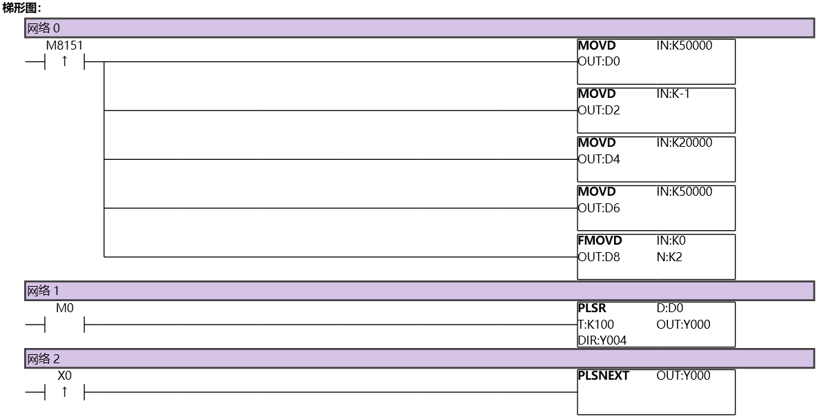
图3 PLSR21
图4 PLSR22
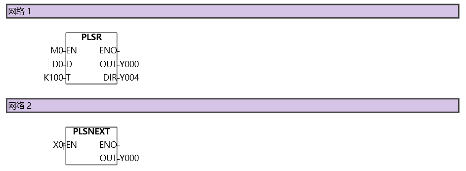
图5 PLSR23